Electromagnetic flow meter

a flow meter and electromagnetic technology, applied in the field of electromagnetic flow meter, can solve the problems of high process cost, large formation cost, advanced forming technique, etc., and achieve the effect of reducing process cost, reducing material cost, and low cos

Active Publication Date: 2009-07-16
KK TOSHIBA
View PDF6 Cites 26 Cited by
  • Summary
  • Abstract
  • Description
  • Claims
  • Application Information

AI Technical Summary

Benefits of technology

[0023]According to the present invention, it is possible to provide an electromagnetic flow meter in which a resin lining is prevented from detaching from a measurement pipe at low costs while using simple process techniques and forming techniques.
[0024]Specifically, it is possible to reduce process costs because it is easy to process the semicircular, rectangular or triangular grooves on the inner surface of the measurement pipe.
[0025]Moreover, it is possible to reduce material costs because, unlike conventional electromagnetic flow meter, the electromagnetic flow meter of the invention does not employ a cylindrical porous plate.
[0026]Moreover, it is easy to manufacture the electromagnetic flow meter because an advanced canning technique is not required.
[0027]Further, it is possible to form the resin lining without using an advanced forming technique.
[0028]In addition, the resin in the semicircular, rectangular or triangular grooves exerts an anchoring effect to suppress detachment of the resin lining portion from the measurement pipe. The resin in the semicircular, rectangular or triangular grooves also constitutes ribs for reinforcing the lining, which exerts a reinforcing effect to prevent the resin lining from crushing inward due to a negative pressure when the pressure inside the measurement pipe turns into negative, for example.

Problems solved by technology

As a result, these techniques require large costs for formation as well as the advanced forming techniques.
However, process costs will become higher when numerous dovetail grooves are formed.
Moreover, even if the dovetail grooves are successfully formed at the ends of the measurement pipe, it is still difficult to form the dovetail grooves deep inside the measurement pipe.
Accordingly, large costs are required for formation.

Method used


Image

  • Electromagnetic flow meter
  • Electromagnetic flow meter
  • Electromagnetic flow meter

Examples


first embodiment

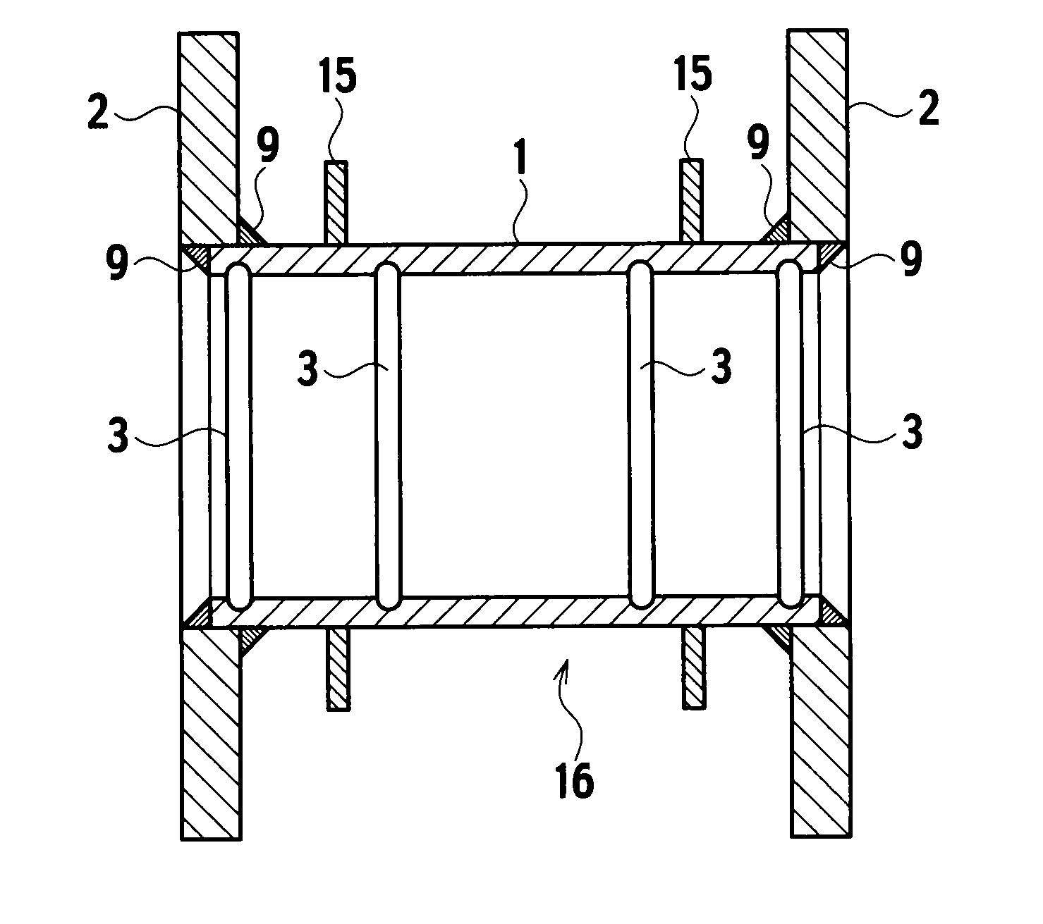
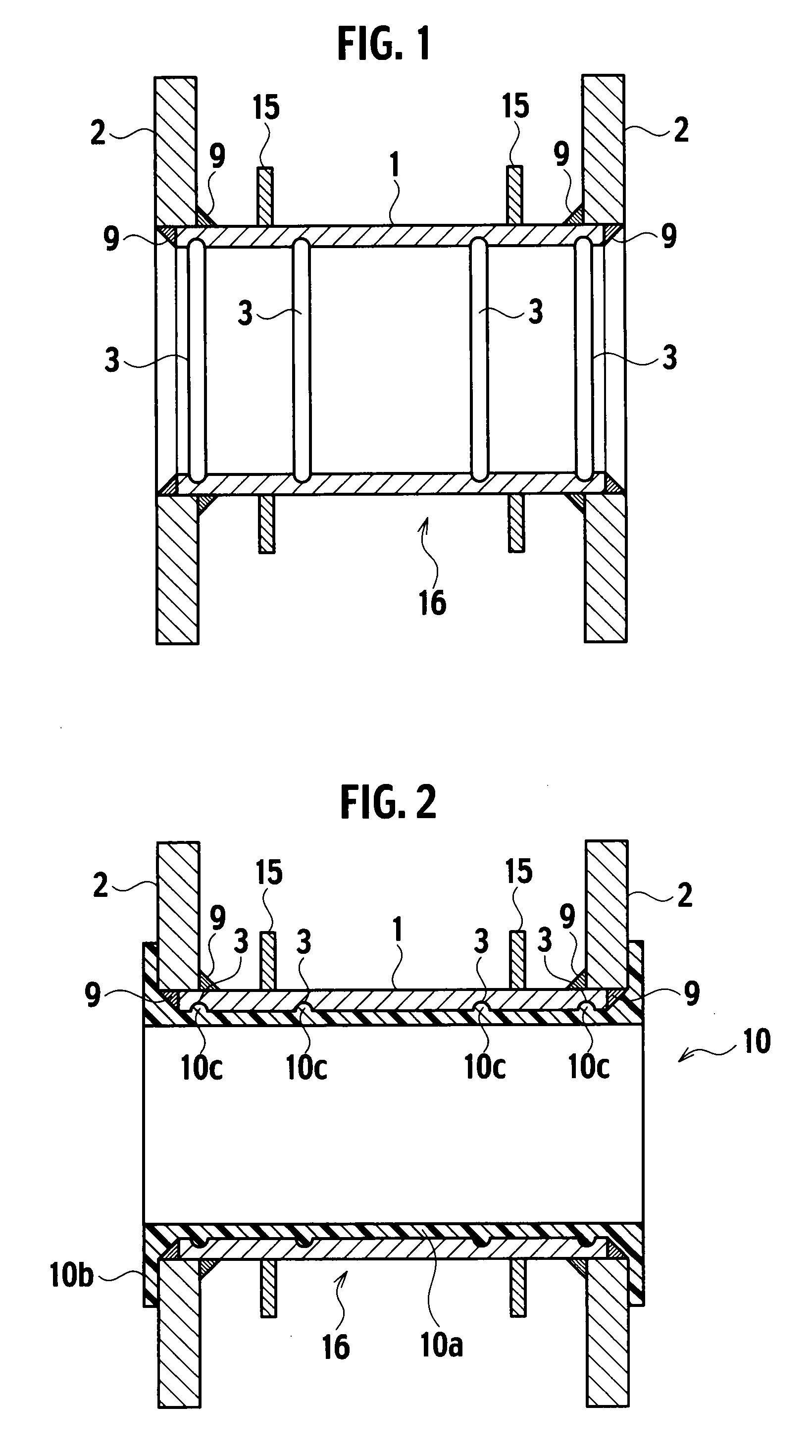
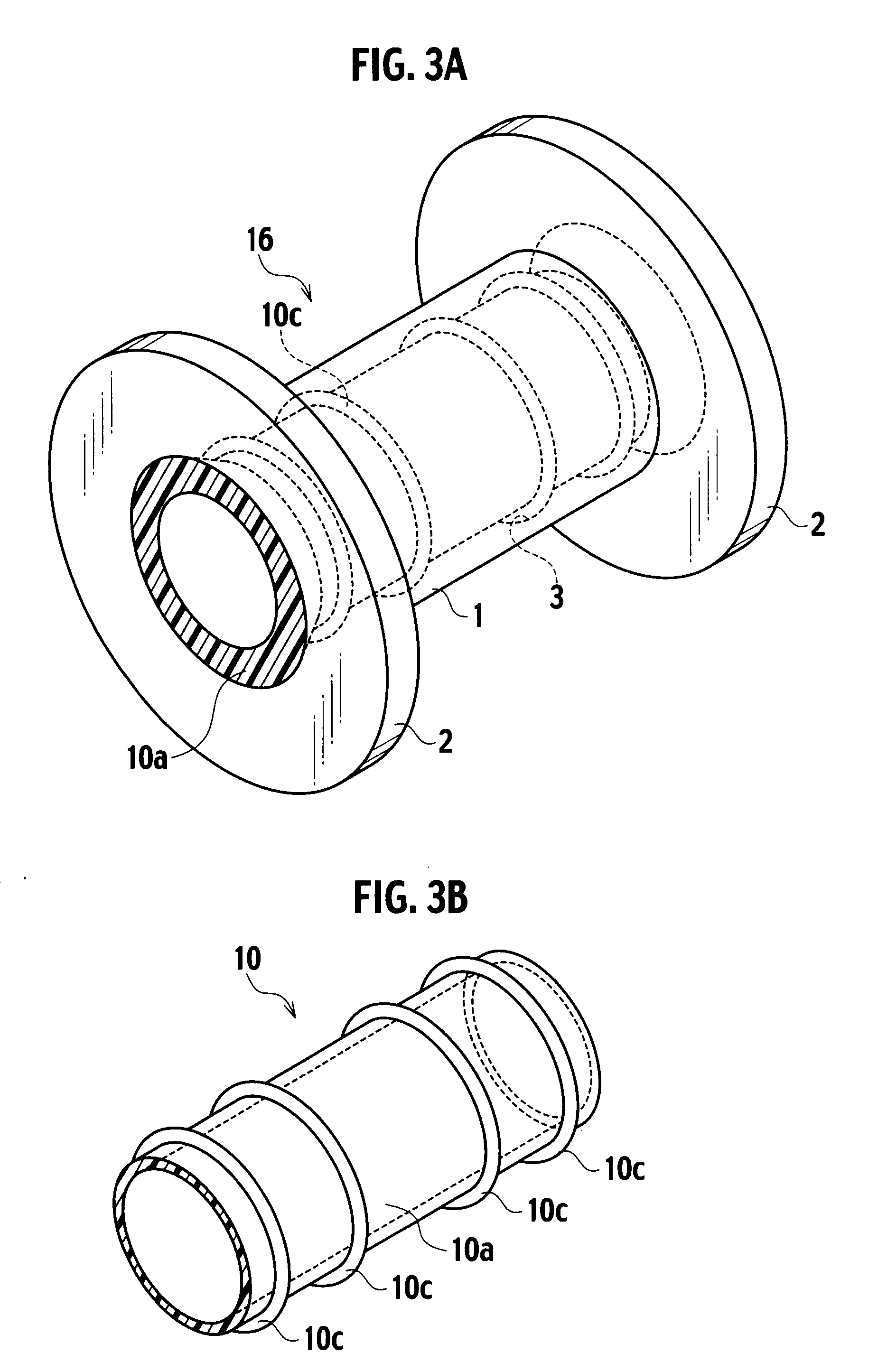
[0049]As shown in FIG. 1, a pipe body 16 includes a measurement pipe 1 in which a measurement target fluid is to flow, a pair of flanges 2 welded on both ends of the measurement pipe 1 and connected to pipes (not shown), and a pair of contents housing chamber plates 15 welded on an outer peripheral surface of the measurement pipe 1 and configured to define a chamber for housing contents such as coils. The measurement pipe 1 is made of metal or insulator such as ceramic material or the like. Multiple grooves 3 whose cross-section is a semicircular shape (hereinafter referred to as “semicircular grooves”) are provided in a circumferential direction on an inner surface of the measurement pipe 1. Here, reference numeral 9 denotes a welded portion.

[0050]The pipe body 16 shown in FIG. 1 is applied with a resin lining made of fluororesin, polyurethane resin or the like. The resin lining 10 can be applied by using a publicly known method, such as a method of fitting molds to both ends and t...

second embodiment

[0064]In the following description, the same constituents as those in the configuration of the electromagnetic flow meter according to the first embodiment will be designated by the same reference numerals used in the first embodiment, and duplicate explanations will be omitted.

[0065]As shown in FIG. 7, in an electromagnetic flow meter according to the second embodiment of the present invention, a groove 8 whose cross-section is a rectangular shape inclined relative to the inner surface of the measurement pipe 1 at a predetermined angle (hereinafter referred to as an “end inclined rectangular groove”) is formed at a ridge portion formed by a cut surface of an end and by the inner surface, of the measurement pipe 1 of the electromagnetic flow meter according to the first embodiment. The resin lining 10 is applied such that the resin enters the end inclined rectangular groove 8.

[0066]As shown in FIG. 8, if there is no end inclined rectangular groove 8, the end of the resin lining port...

third embodiment

[0068]FIGS. 9 to 11 show a third embodiment of the present invention. In the following description, the same constituents as those in the configuration of the electromagnetic flow meter according to the first embodiment will be designated by the same reference numerals used in the first embodiment, and duplicate explanations will be omitted.

[0069]As shown in FIGS. 9 to 11, grooves 12 each whose cross-section is a semicircular shape (hereinafter referred to as “flange seating face semicircular grooves”) are formed on a surface of a flange seat 11 provided on the flange 2. The flange seating face semicircular grooves 12 are provided so as to extend radially from a central axis O of the measurement pipe 1. The lining flare portion 10b is formed on the surface of the flange seat 11. The lining flare portion 10 may be formed so as to be integrally connected to the resin lining portion 10a.

[0070]The resin entered the flange seating face semicircular grooves 12 functions as ribs for reinf...


PUM


Abstract

An electromagnetic flow meter has a pipe body 16 in which a measurement target fluid flows. The pipe body 16 includes: a measurement pipe 1 having a groove 3 whose cross-section is any of a semicircular shape, a rectangular shape, and a triangular shape formed on an inner surface in a circumferential direction; and a resin lining portion 10a formed on the inner surface of the measurement pipe.

Description

CROSS REFERENCE TO RELATED APPLICATION[0001]This application is based upon and claims the benefit of priority from Japanese Patent Application No. 2008-005241 filed on Jan. 15, 2008, the entire contents of which are incorporated herein by reference.BACKGROUND OF THE INVENTION[0002]1. Field of the Invention[0003]The present invention relates to an electromagnetic flow meter configured to measure a flow rate of a fluid. More specifically, the present invention relates to a technique to apply a resin lining on an inner surface of a measurement pipe in which a measurement target fluid is to flow.[0004]2. Description of the Related Art[0005]An electromagnetic flow meter is configured to measure a flow rate by applying an electric current to a coil to generate a magnetic field inside a measurement pipe, and by detecting magnitude of an electromotive force generated in proportion to the electric conductivity of a liquid flowing inside the measurement pipe. Generally, a resin lining made of...

Claims


Application Information

Patent Timeline
Patent Type & Authority Applications(United States)
IPC IPC(8): G01F1/58
CPCG01F1/58G01F1/05
Inventor IIJIMA, TAKUYA
Owner KK TOSHIBA
Why Eureka
Try Eureka