Ethernet switching method and ethernet switch

a technology of ethernet frames and switching methods, applied in the direction of data switching networks, digital transmission, electrical equipment, etc., can solve the problem of inability to transmit ethernet frames at regular intervals, and achieve the effect of ensuring the quality of servi

Inactive Publication Date: 2009-07-16
NEW H3C TECH CO LTD
View PDF6 Cites 25 Cited by
  • Summary
  • Abstract
  • Description
  • Claims
  • Application Information

AI Technical Summary

Benefits of technology

[0023]An Ethernet port in accordance with the present invention is divided into at least two transmission time slots of the same length and to-be-transmitted Ethernet frames of fixed length are switched to the queue of the transmission time slots at the Ethernet ports corresponding to the L2 / L3 information of the Ethernet frames, since the Ethernet frames of fixed length in a transmission time slot are transmitted when the regular transmission interval of the transmission time slot expires, the method of the present invention meets the transmission delay requirement of time-division services transmitted at constant rate over Ethernet. The length of the Ethernet frames is fixed and the transmission periods of the transmission time slots are due regularly in a cyclic order, therefore the transmission delay of an Ethernet frame of fixed length will always remain unchanged. In addition, the transmission time slots can be associated with service streams so that the Ethernet frames of one same service stream can be transmitted at regular intervals and the transmission rate of the service stream remains constant, in this way the Quality of Service (QoS) is ensured. It can be seen that the Ethernet switching method of the present invention allows time-division services to be transmitted at constant rate over Ethernet while keeping the present Ethernet switching mechanism.

Problems solved by technology

Inconstant switching delay makes it impossible to transmit Ethernet frames at regular intervals.

Method used


Image

  • Ethernet switching method and ethernet switch
  • Ethernet switching method and ethernet switch
  • Ethernet switching method and ethernet switch

Examples


embodiment 1

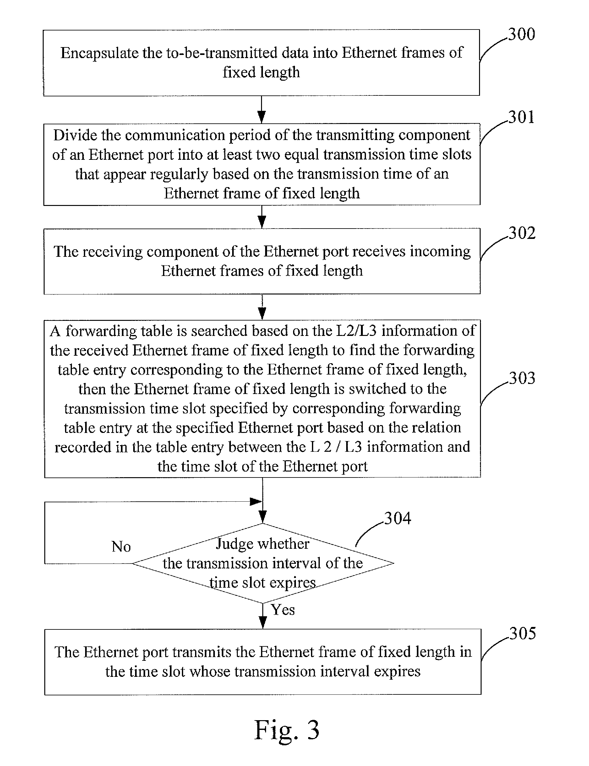
[0059]FIG. 3 is a flow chart of the Ethernet switching method in Embodiment 1 of the present invention. As shown in FIG. 3, the method includes the following steps.

[0060]Step 300: the to-be-transmitted upper layer data are encapsulated into Ethernet frames of fixed length.

[0061]First of all, time-division switching over Ethernet requires Ethernet frames of fixed length.

[0062]When the to-be-transmitted upper layer data have been encapsulated with the conventional Ethernet frame encapsulation method, if the length of the Ethernet frames of to-be-transmitted upper layer data is smaller than or equal to the length that the Ethernet frames of fixed length can carry, the to-be-transmitted upper layer data shall be encapsulated directly into Ethernet frames of fixed length; if the length of the Ethernet frames of to-be-transmitted upper layer data is larger than the length that the Ethernet frames of fixed length can carry, the to-be-transmitted upper layer data shall be fragmented by usin...

embodiment 2

[0138]In this embodiment, an Ethernet switching method combining the time-division switching and the packet switching is illustrated.

[0139]In practical applications, the transmission time slots at an Ethernet port can be configured to designate some transmission time slots as time-division switching time slots for time-division services in time-division switching, and the rest transmission time slots shall carry burst service streams in the packet switching, hence the transmission time slots at the Ethernet port are not all dedicated to the time-division service streams transmitted at constant rate.

[0140]FIG. 12 is a flow chart of the Ethernet switching method in Embodiment 2 of the present invention. As shown in FIG. 12, the method includes the following steps.

[0141]Step 1200: the to-be-transmitted upper layer data are encapsulated into Ethernet frames of fixed length.

[0142]The format and encapsulation method of the Ethernet frames of fixed length are identical with the format and ...


PUM


Abstract

The present invention discloses an Ethernet switching method, including: dividing a communication period of a transmitting component of an Ethernet port into at least two equal transmission time slots that appear regularly; deciding a transmission time slot at the Ethernet port corresponding to the Layer 2/Layer 3 (L2/L3) information of a to-be-switched Ethernet frame of fixed length; switching the to-be-switched Ethernet frame of fixed length into a time-division switch transmission queue maintained by the decided Ethernet port in the decided transmission time slot; and transmitting, by the Ethernet port in a cyclic order, to-be-switched Ethernet frames of fixed length in time-division switch transmission queues maintained in different transmission time slots separately. The present invention also discloses an Ethernet switch. The Ethernet switching scheme provided by the present invention satisfies the transmission delay requirement of time-division services transmitted at constant rate.

Description

FIELD OF THE TECHNOLOGY[0001]The present invention relates to service data packet switching technology, and particularly, to an Ethernet switching method and an Ethernet switch.BACKGROUND OF THE INVENTION[0002]The data services in the domain of data switching of the conventional network can be divided into burst services and time-division services. The burst services are data services transmitted at non-constant rate which allows comparatively greater end-to-end transmission delay variation; and the time-division services are data services transmitted at constant rate which allows smaller end-to-end transmission delay variation.[0003]Data in the burst services are usually transmitted via packet switching technology on Layer 2 / Layer 3 (L2 / L3) at present. Such switching technology has the advantages of high bandwidth efficiency and low cost. Ethernet switches such as Local Area Network (LAN) Switches are widely used as important packet switch devices in LAN as well as in Metropolitan ...

Claims


Application Information

Patent Timeline
Patent Type & Authority Applications(United States)
IPC IPC(8): H04L12/56
CPCH04L12/4633H04L47/562H04L49/351H04L49/3072H04L49/254
Inventor YU, YANGWANG, WEILI, JINGLINWEI, CHUSHUN
Owner NEW H3C TECH CO LTD
Why Eureka
Try Eureka