System for distributing broadband wireless signals indoors

a wireless signal and indoor technology, applied in the field of telecommunications, can solve the problems of not being able to adapt to changes in communications standards, devices cannot guarantee coverage in any enclosure, and cannot be remotely supervised and controlled

Inactive Publication Date: 2011-06-30
TELEFONICA SA
View PDF22 Cites 9 Cited by
  • Summary
  • Abstract
  • Description
  • Claims
  • Application Information

AI Technical Summary

Benefits of technology

[0017]The present invention has the object of resolving the aforementioned problems by a system for distributing radio signals indoors, guaranteeing the remote coverage, supervision and configuration of all equipment used and ensuring service quality, also allowing updates to new standards without the need for changes of equipment.

Problems solved by technology

These devices must be configured by the user and cannot be updated to changes in the communications standard they use.
Furthermore, these devices do not guarantee coverage in any enclosure and cannot be remotely supervised and controlled from the operator's network, so that they require local configuration thereof by the user.
With current technology, these devices and these roll-out techniques suffer from limitations that are described below:
It is not possible to guarantee radio coverage in all enclosures.
It is not possible to guarantee the remote supervision of all devices from the telecommunications operator's network.
It is not possible to guarantee the quality of the service offered.
It is necessary to have the existence of as many devices as communications interfaces one wants to have, with the subsequent accumulation of devices and costs increase.
The devices are specific for each radio standard and cannot be updated, so that in the event of improvements in the standard or the appearance of new standards, it is necessary to discard the devices and acquire new ones.

Method used


Image

  • System for distributing broadband wireless signals indoors
  • System for distributing broadband wireless signals indoors
  • System for distributing broadband wireless signals indoors

Examples


Embodiment Construction

[0040]Throughout this specification, the term “comprises” and its derivatives must not be interpreted in an excluding or limiting sense, i.e. it should not be interpreted in the sense of excluding the possibility that the element or concept referred to includes additional elements or stages.

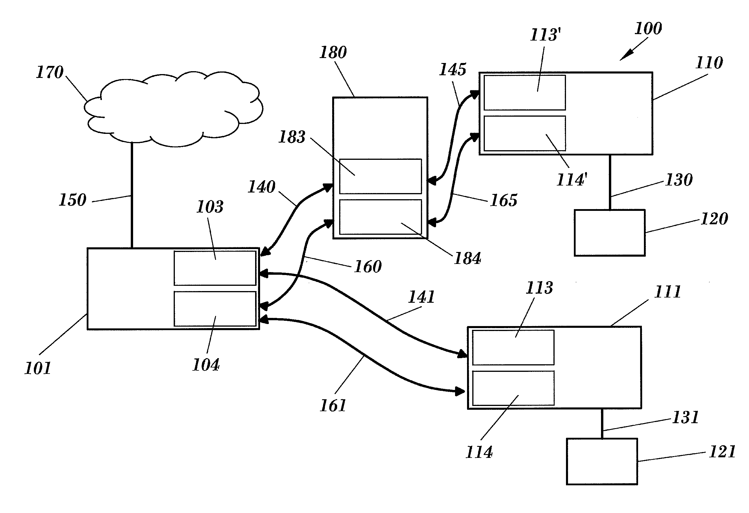
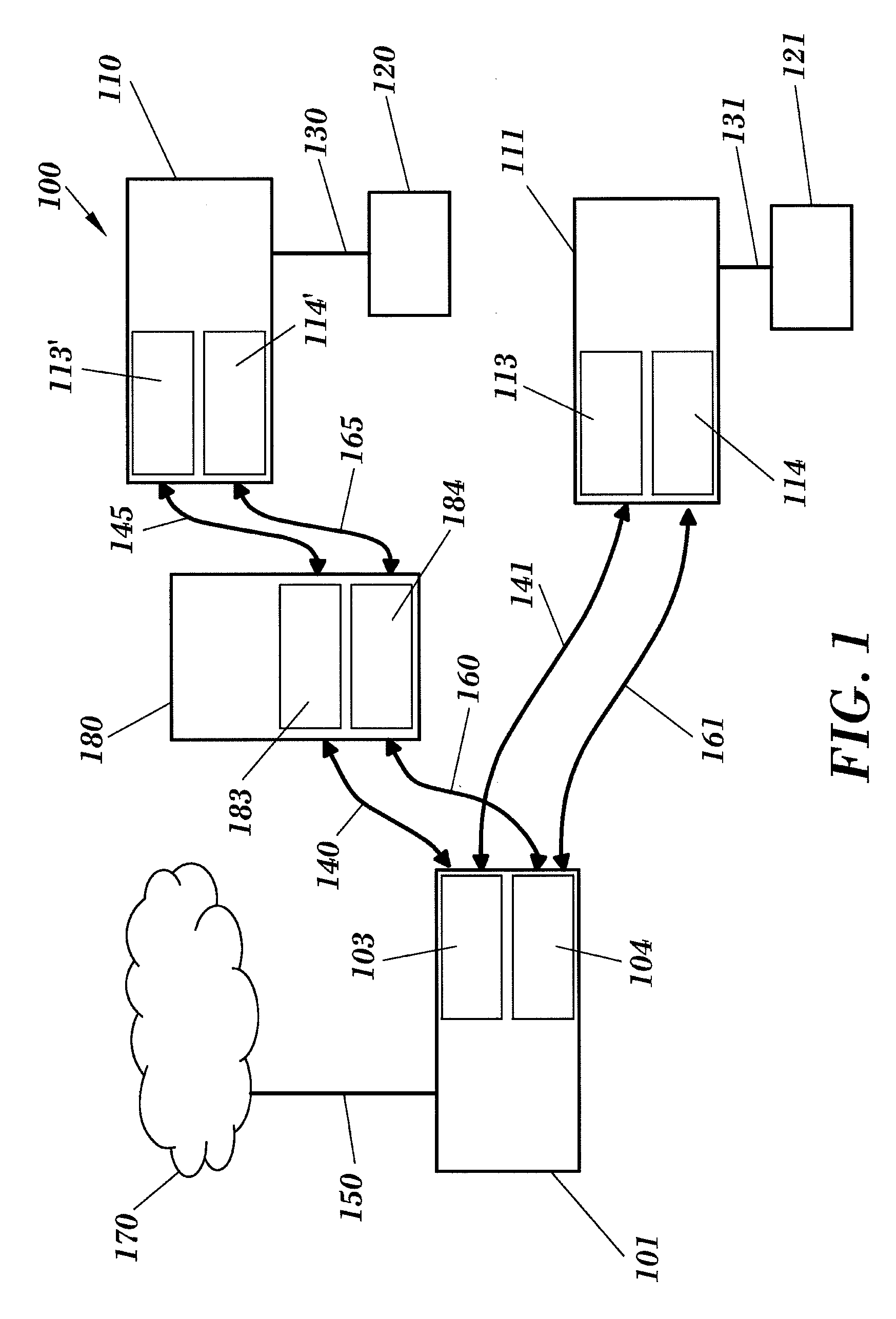
[0041]FIG. 1 illustrates a diagram of a possible embodiment of the system for distributing broadband wireless signals 100 of the invention. The system 100 is especially designed to be used inside buildings and to support multiple radio communication interfaces inside a building. The system 100 comprises the following elements:

[0042]A radio access point or node, also called radio gateway 101. In this radio access node 101 reside the rerouting functions between the radio interfaces within a building and of gateway between the wireless network inside the building and an access network (generally a fixed network, for example copper pair or fibre optic to the home), in addition to the management funct...


PUM


Abstract

system for distributing broadband wireless signals indoors includes a radio access node, connected to a telecommunication access network via an access interface, where said radio access node comprises a broadband-signal-transmitting/-receiving module configured to transmit and receive broadband wireless signals via a broadband radio interface; at least one client device comprising a broadband-signal-transmitting/-receiving module configured to transmit and receive broadband wireless signals to/from said radio access node via said broadband radio interface. It also comprises a control channel configured to exchange control signals between said radio access node and said at least one client device over a control radio interface, each of said radio access nodes and at least one client device comprising a control-signal-transmitting/receiving module configured to establish said control channel for transmitting and receiving wireless signals over said control radio interface.

Description

FIELD OF THE INVENTION[0001]The present invention is applied to the field of telecommunications and, more specifically, to the construction and roll-out of communications networks inside buildings and their connection with other telecommunications networks.BACKGROUND OF THE INVENTION[0002]The technique conventionally used to provide radio interfaces inside buildings consists of the installation of as many devices and interfaces as are necessary. These devices must be configured by the user and cannot be updated to changes in the communications standard they use. Furthermore, these devices do not guarantee coverage in any enclosure and cannot be remotely supervised and controlled from the operator's network, so that they require local configuration thereof by the user.[0003]Some examples of devices which have said drawbacks are:[0004]A device which permits access to the telecommunications network by copper pair and ADSL interface, and that inside the home supports the IEEE 802.11x (W...

Claims


Application Information

Patent Timeline
Patent Type & Authority Applications(United States)
IPC IPC(8): H04W40/00
CPCH04W84/045H04W24/02H04L41/24H04W4/20H04W76/10
Inventor CUCALA GARCIA, LUISDAVILA ALVAREZ, PABLO
Owner TELEFONICA SA
Why Eureka
Try Eureka