

Projection system, and projector
a projection system and projector technology, applied in the field of projection systems, can solve problems such as negative effects on image display, and achieve the effect of reducing the effect of image display
- Summary
- Abstract
- Description
- Claims
- Application Information
AI Technical Summary
Benefits of technology
Problems solved by technology
Method used
Image

Examples
first embodiment
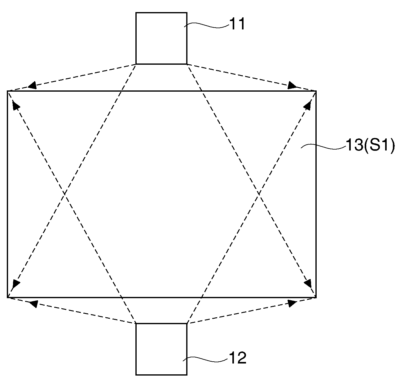
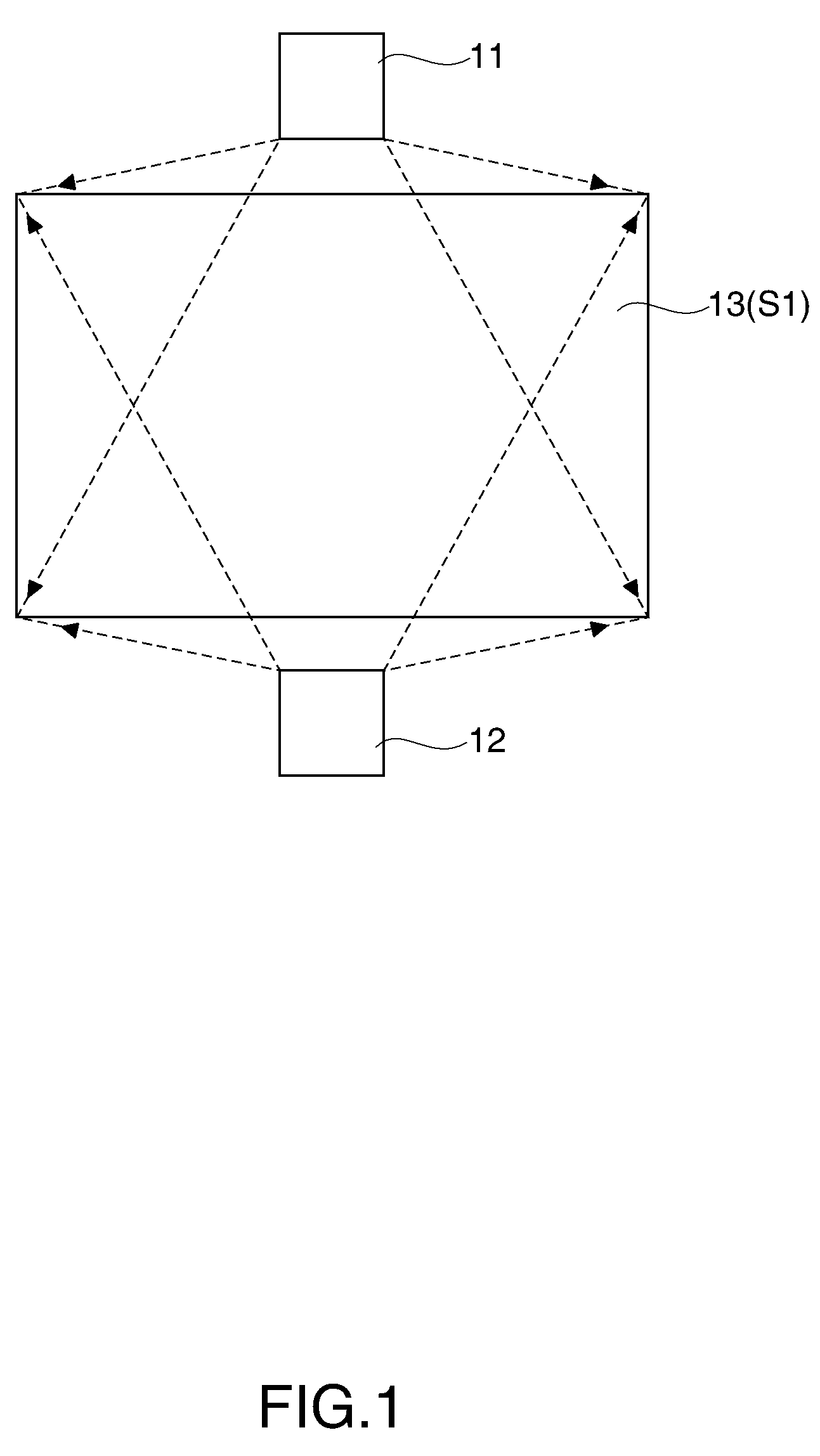
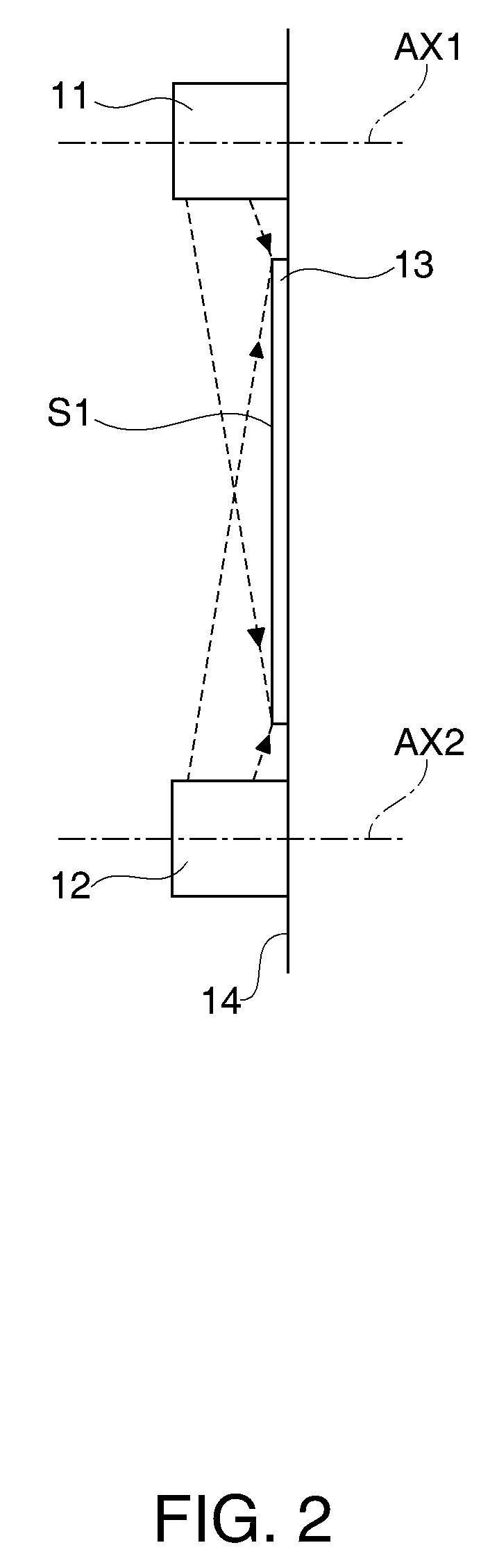
[0043]FIG. 1 illustrates a front structure of a projection system according to a first embodiment of the invention. FIG. 2 is a side structure of the projection system shown in FIG. 1. The projection system includes a first projector 11 and a second projector 12. The first projector 11 and the second projector 12 are attached to a common wall surface 14. The first projector 11 and the second projector 12 project light to a screen 13 attached to the wall surface 14.
[0044]The screen 13 is disposed such that a light receiving surface S1 faces on the side opposite to the side fixed to the wall surface 14. Also, the screen 13 is positioned such that the light receiving surface S extends substantially in parallel with the wall surface 14. The first projector 11 is located above the screen 13 in the vertical direction. The second projector 12 is located below the screen 13 in the vertical direction. Both the first projector 11 and the second projector 12 are positioned in the vicinity of t...
second embodiment
[0076]FIG. 11 illustrates a front structure of a projection system according to a second embodiment of the invention. The projection system in this embodiment is characterized by including a detection camera 55. Similar reference numbers are given to parts similar to those in the first embodiment, and the same explanation is not repeated herein. The detection camera 55 functions as a detection unit for detecting light entering the light receiving surface S1 from the first projector 11. The detection camera 55 is disposed in the vicinity of the first projector 11. The detection camera 55 has a plurality of light receiving elements (not shown) which convert entering light into electronic signals. The detection camera 55 is constituted by CCD or CMOS sensor, for example.
[0077]The projection system displays images using only light emitted from the first projector 11 as long as the light supplied from the first projector 11 is not blocked by an object. The detection camera 55 obtains an ...
third embodiment
[0087]FIG. 16 is a side structure of a projection system according to a third embodiment of the invention. The projection system in this embodiment is characterized in that a part of a floor surface 73 is a light receiving surface S2. The same explanation as in those the above embodiments is not repeated herein. A first projector 71 and a second projector 72 are attached onto the floor surface 73. The first projector 71 and the second projector 72 supply light to an area between the first projector 71 and the second projector 72 on the floor surface 73. The first projector 71 and the second projector 72 are disposed opposed to each other at positions facing the area through which light travels toward the light receiving surface S2.
[0088]The first projector 71 and the second projector 72 both direct light to be supplied to the light receiving surface S2 in the directions along the light receiving surface S2. The first projector 71 and the second projector 72 have structures similar t...
PUM
 Abstract
Description
Claims
Application Information