Electro-wetting display panel

Inactive Publication Date: 2009-07-23
IND TECH RES INST
View PDF2 Cites 17 Cited by
  • Summary
  • Abstract
  • Description
  • Claims
  • Application Information

AI Technical Summary

Benefits of technology

[0009]Accordingly, the present invention is directed to an electro-wetting display panel with high aperture ratio and high display contrast.
[0010]The present invention is directed to an electro-wetting display panel which allows the color fluid to move towards a predetermined direction so as to improve the stability of driving and get high uniformity.
[0011]The present invention provides an electro-wetting display panel including a first substrate, an insulator layer, a second substrate, a plurality of partitioning structures, and a plurality of electro-wetting display mediums. The first substrate has a plurality of first electrodes. The insulator layer is disposed on the first substrate to cover the first electrodes. The second substrate located above the first substrate has a plurality of second electrodes. The insulator layer is disposed between the first electrodes and the second electrodes and provides electric capacitance accumulation effect. The partitioning structures are disposed on the insulator layer, and each of the partitioning structures respectively defines a pixel region. In addition, at least one of the partitioning structures has a flow channel surrounding the pixel regions, and the flow channel is connected to one of the pixel regions correspondingly. The electro-wetting display mediums are located in the pixel regions and the flow channels. When the electro-wetting display mediums are driven by the first electrodes and the second electrodes, the electro-wetting display mediums flows between the pixel regions and the flow channels.
[0012]Th

Problems solved by technology

Besides, the traditional panel structure is easy to cause the color fluid 132 random move because of the s

Method used


Image

  • Electro-wetting display panel
  • Electro-wetting display panel
  • Electro-wetting display panel

Examples


Example

First Embodiment

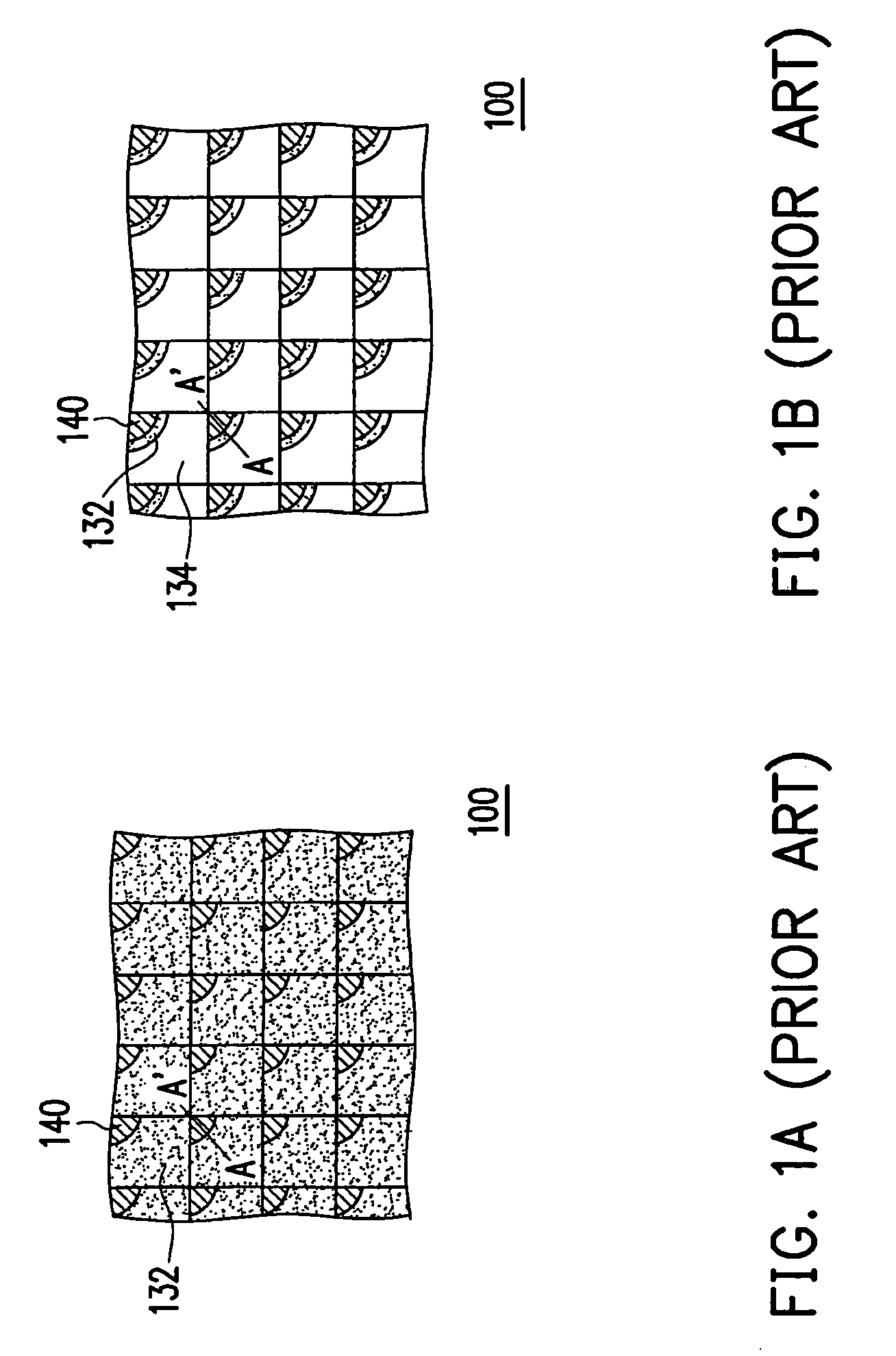
[0025]FIG. 2A is a partial view of an electro-wetting display panel according to the first embodiment of the present invention, and FIG. 2B is a cross-sectional view of the electro-wetting display panel in FIG. 2A along line B-B′. Referring to FIG. 2A and FIG. 2B, in the present embodiment, the electro-wetting display panel 200 includes a first substrate 210, an insulator layer 220, a second substrate 230, a plurality of partitioning structures 240, and a plurality of electro-wetting display mediums 250. The second substrate 230 is located above the first substrate 210, and the insulator layer 220, the partitioning structures 240, and the electro-wetting display mediums 250 are disposed between the first substrate 210 and the second substrate 230, as shown in FIG. 2B.

[0026]As shown in FIG. 2A and FIG. 2B, the first substrate 210 has a plurality of first electrodes 212. In the present embodiment, the first electrodes 212 may be transparent electrodes, reflective elect...

Example

Second Embodiment

[0034]FIG. 4A is a partial view of an electro-wetting display panel according to the second embodiment of the present invention, and FIG. 4B is a cross-sectional view of the electro-wetting display panel in FIG. 4A along line C-C′. Referring to FIG. 4A and FIG. 4B, the electro-wetting display panel 400 has similar structure as the electro-wetting display panel 200, wherein like reference numerals refer to like elements. The difference between the two electro-wetting display panels is that the electro-wetting display panel 400 has a partition 440 and the partition 440 is different from the partitioning structures 240 in the electro-wetting display panel 200. The insulator layer 220, the partition 440, and the electro-wetting display mediums 250 are disposed between the first substrate 212 and the second substrate 232, as shown in FIG. 4B. In addition, the dispositions of the first electrodes 212 and the second electrodes 232 of the electro-wetting display panel 400 a...

Example

Third Embodiment

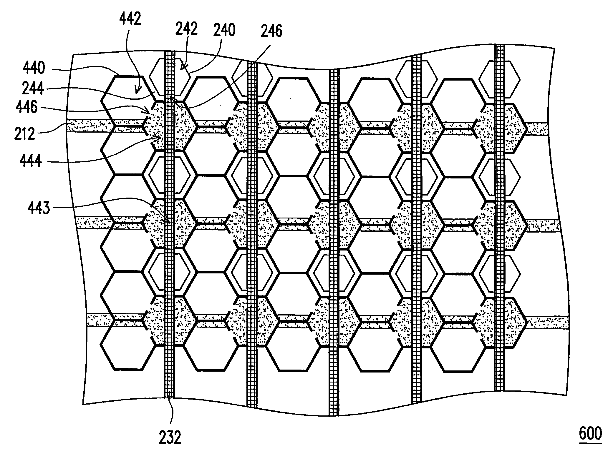
[0040]FIG. 6 is a partial View of an electro-wetting display panel according to the third embodiment of the present invention. Referring to FIG. 6, the structure of the electro-wetting display panel 600 is similar to that of the electro-wetting display panel 200 or 400, wherein like reference numerals refer to like elements. The difference between the electro-wetting display panel 600 and the electro-wetting display panel 200 or 400 is that the electro-wetting display panel 600 has a combined design of the partitioning structures in the electro-wetting display panel 200 and the partition in the electro-wetting display panel 400, as shown in FIG. 2A, FIG. 4A, and FIG. 6.

[0041]To be specific, when the electro-wetting display panel 600 is driven, the color fluid 252 in some of the pixel regions 242 is stored into the flow channels 244 through the aperture 246 according to the design of the partition structures 240, and the color fluid 252 in some of the pixel regions 44...


PUM


Abstract

An electro-wetting display panel including a first substrate, an insulator layer, a second substrate, partitioning structures, and electro-wetting display mediums. The first substrate has a plurality of first electrodes. The insulator layer is disposed on the first substrate to cover the first electrodes. The second substrate located above the first substrate and has a plurality of second electrodes. The partitioning structures are disposed on the insulator layer and each defines a pixel region, respectively. At least one of the partitioning structures has a flow channel surrounding the pixel regions, and the flow channel is connected to one of the pixel regions correspondingly. The electro-wetting display mediums are disposed within the pixel regions and the flow channels. When the electro-wetting display mediums are driven by the electric charge between the first electrodes and the second electrodes, the electro-wetting display mediums move between the pixel regions and the flow channels.

Description

CROSS-REFERENCE TO RELATED APPLICATION[0001]This application claims the priority benefit of Taiwan application serial no. 97102336, filed on Jan. 22, 2008. The entirety of the above-mentioned patent application is hereby incorporated by reference herein and made a part of this specification.BACKGROUND OF THE INVENTION[0002]1. Field of the Invention[0003]The present invention generally relates to a display panel, in particular, to an electro-wetting display panel.[0004]2. Description of Related Art[0005]Different types of display panels are constituted based on different display mechanisms. Presently, the most well-known display panels include liquid crystal display (LCD) panels, plasma display panels, field emission display panels, organic light emitting display panels, and electro-wetting display panels, wherein the development of electro-wetting display panels has become much focus because electro-wetting display panels have many advantages in performance and cost, for its high co...

Claims


Application Information

Patent Timeline
IPC IPC(8): G02F1/01
CPCG02B26/005
Inventor CHENG, CHAO-KAICHIU, WAN-WENCHENG, WEI-YUANWANG, CHUNG-WEILU, JHIH-PING
Owner IND TECH RES INST
Why Eureka
Try Eureka