
Crystal Display Shielded by One or More Protective Guards

Inactive Publication Date: 2009-07-23
NIKE INC
View PDF19 Cites 15 Cited by
  • Summary
  • Abstract
  • Description
  • Claims
  • Application Information

AI Technical Summary

Benefits of technology

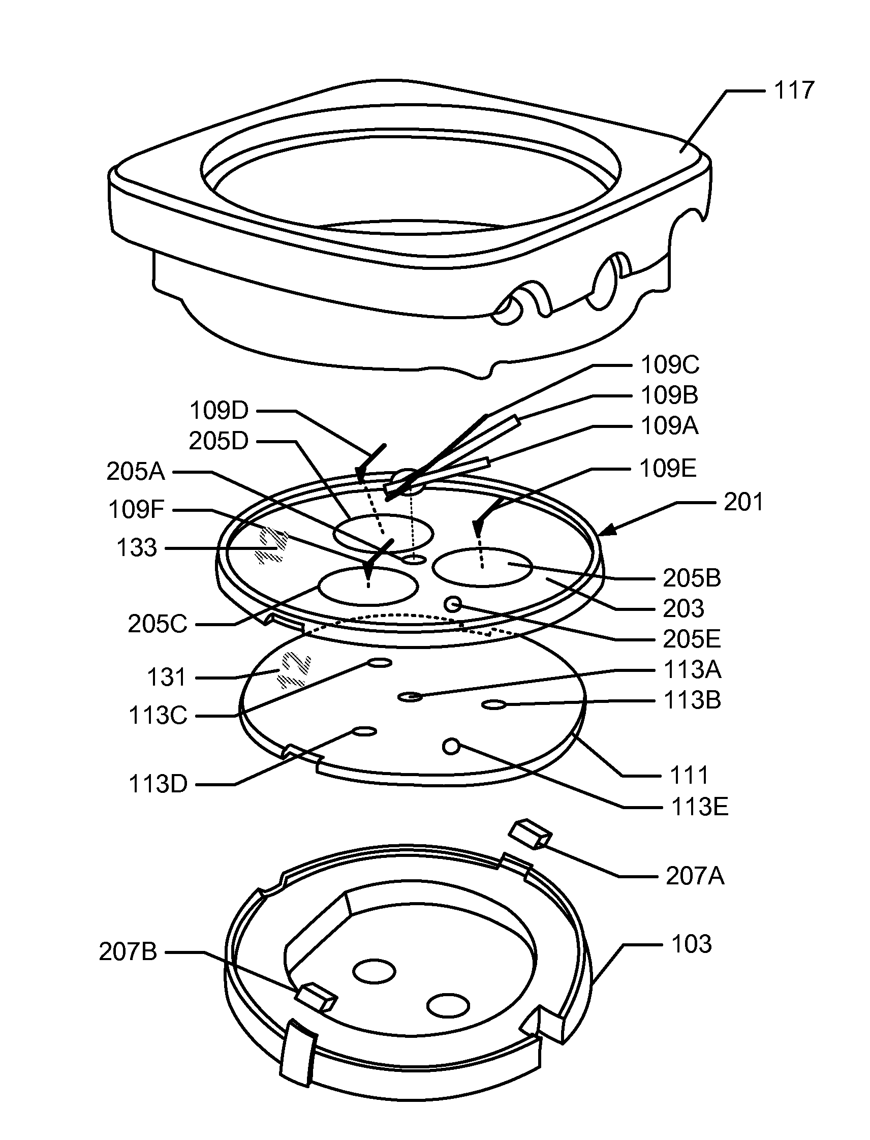
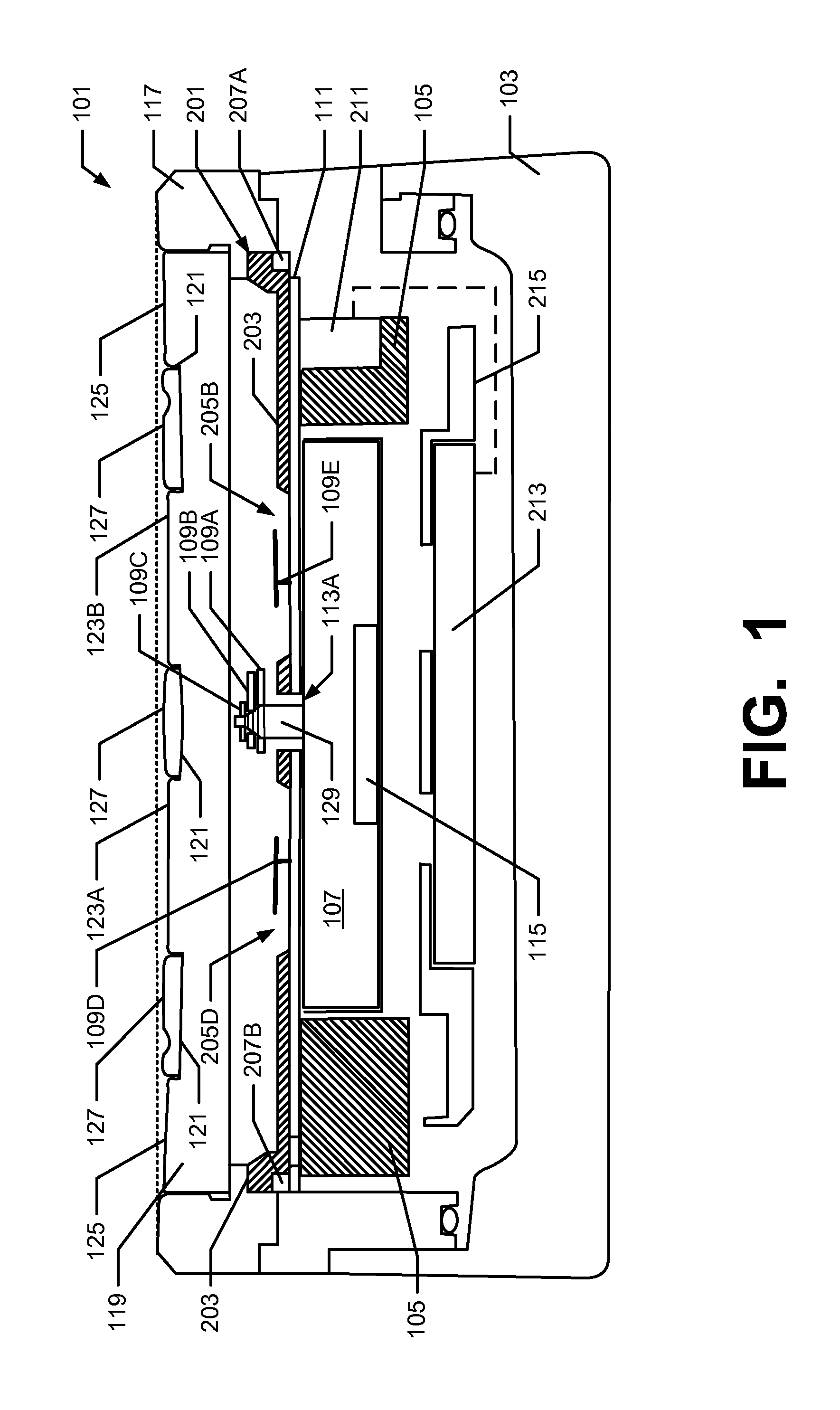
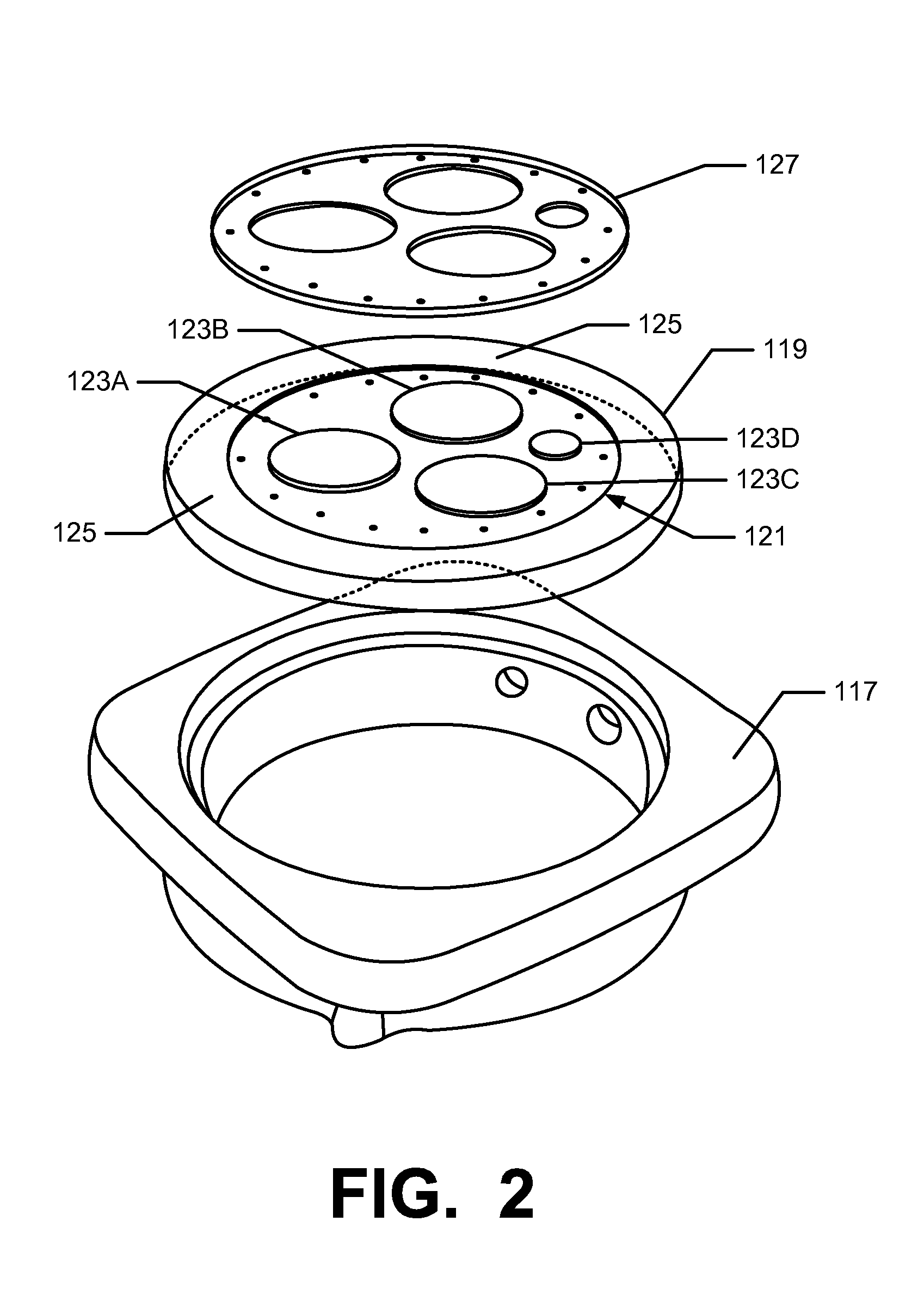
[0004]Various aspects of this invention relate to structures that can shield an instrument's crystal from damage while still allowing the instrument display underneath the crystal to be accurately viewed. According to some implementations of the invention, for example, an instrument is provided with a bezel surrounding a crystal (optionally, a concave crystal), so that the upper surface of the bezel extends above the upper surface of the crystal. Still further, a protective guard may be embedded into or otherwise provided at various locations and portions of the crystal, so that an upper surface of the protective guard extends above the upper surface of the crystal. By manufacturing the bezel and the guard from hard materials, such as metal, or from impact-attenuating materials, such as a foam, the crystal can be shielded from scratching, gouging, and other types of damage.

Problems solved by technology

The usefulness of most instruments, however, is limited by their visibility.
For example, if the crystal covering the display becomes scratched, gouged, or otherwise damaged, then it may be difficult for the user to view the display below the crystal and / or it may be difficult to protect the underlying displays and mechanisms from damage (e.g., due to moisture, dirt, debris, impact, etc.).
These materials, however, typically are very expensive and are only partially resistant to scratching.

Method used


Image

  • Crystal Display Shielded by One or More Protective Guards
  • Crystal Display Shielded by One or More Protective Guards
  • Crystal Display Shielded by One or More Protective Guards

Examples


Embodiment Construction

[0010]I. General Description of Watches and Other Instruments in Accordance with Examples of the Invention

[0011]In the following description of various example structures in accordance with the invention, reference is made to the accompanying drawings, which form a part hereof, and in which are shown by way of illustration various example instrument assemblies in accordance with the invention. Additionally, it is to be understood that other specific arrangements of parts and structures may be utilized, and structural and functional modifications may be made without departing from the scope of the present invention. Also, while the terms “top,”“bottom,”“front,”“back,”“rear,”“side,”“underside,”“overhead,” and the like may be used in this specification to describe various example features and elements of the invention, these terms are used herein as a matter of convenience, e.g., based on the example orientations shown in the figures and / or the orientations in typical use. Nothing in t...


PUM


Abstract

Structures are disclosed that can improve the visibility of instrument displays. With some implementations, an instrument is provided with a bezel surrounding a crystal, wherein the upper surface of the bezel extends above the upper surface of the crystal. Also, a guard system may be embedded into and / or otherwise provided at portions of the crystal, wherein an upper surface of the guard also extends above the upper surface of the crystal.

Description

FIELD OF THE INVENTION[0001]The present invention relates to structures for improving the visibility of instruments, such as wristwatches, other wrist-borne devices, portable electronic devices, and the like. Various examples of the invention may be particularly applicable for protecting a surface of a watch crystal or other display device from being scratched or otherwise damaged.BACKGROUND OF THE INVENTION[0002]A variety of instruments are commonly used in modern society. Many adults, for example, will wear some type of wristwatch. Many people also will frequently wear or carry portable electronic devices, such as wireless telephones, digital music players, and personal digital assistants (PDAs). Still other types of instruments, such as pedometers, compasses, and satellite positioning devices, may be carried by individuals, e.g., during athletic activities, such as running, hiking, boating, and biking. Typically, these instruments include a mechanism, a display, and a transparent...

Claims


Application Information

Patent Timeline
IPC IPC(8): G02B7/00
CPCG04B19/28G04B39/006G04B39/00G04B37/0008
Inventor HARLEY, JR., RICHARD D.
Owner NIKE INC
Learn More