Design software incorporating efficient 3-D rendering

a design software and efficient technology, applied in the field of system, method and computer program products for modeling, can solve the problems of inefficiency, design is physically impossible or impractical, roof or ceiling collapse, etc., and achieve accurate visual effect data, accurate and efficient rendering of three-dimensional views

Active Publication Date: 2007-07-24
ARMSTRONG WORLD INDUSTRIES +1
View PDF8 Cites 31 Cited by
  • Summary
  • Abstract
  • Description
  • Claims
  • Application Information

AI Technical Summary

Benefits of technology

[0014]For example, a method in accordance with an implementation of the present invention of accurately and efficiently rendering three-dimensional views of a user's design choices involves receiving user input regarding the positioning of a design element in a design space. Generally, the user input includes one or more attributes associated with the design element. For example, the user input can relate to where a desk goes in relation to a wall, as well as preferences for coloring or material, and the like.
[0015]The method also involves retrieving a blank for the design element from a data store. The blank will generally be a template of a visual effect for the design element, such as for shading, shadowing, or other visual effects that might be expected for a given position of a design element. This method further involves a step for providing an accurate three-dimensional view of the user input at a display device through communication with a graphical processing unit. This step generally involves the graphical processing unit providing a display device with the appropriate information so that the display device can display accurate visual effect data for the design element.
[0017]Accordingly, implementations of the present invention include front-end and run-time (or both) perspectives that ultimately provide a user of design software with a believable, realistic depiction of design choices in real-time, or as the user is designing a design space. This accurate and real-time creation of the user's design choices can ensure elements are placed in physically appropriate locations, and can also ensure that elements are positioned with functional and ergonomic considerations in mind.

Problems solved by technology

For example, one typical software design program might allow an architect to design a roof or ceiling that is ill-suited for the number or type of weight-bearing walls the architect has presently drawn.
If the roof were actually constructed as designed by the architect, the roof or ceiling might collapse.
In a situation such as this, however, the builder might indicate to the architect that the design is physically impossible or impractical, and ask for a redesign.
This, of course, can lead to any number of inefficiencies.
Part of the problem with many design software programs that can lead to designing physically impractical structures is the notion that many such design problems require some drawing of a space in flat, two-dimensional space.
While three-dimensional rendering is available in some design software, three-dimensional rendering is fairly processing or resource intensive, and can take an additional amount of time.
In particular, traditional rendering programs can take anywhere from several minutes to several hours to appropriately render all of the lighting and shadowing characteristics of a given space with any accuracy.
With this type of system, however, both the determination and rendering are done as the user is making selections in real-time, and, as such, is quite limited in its ability to provide believable, realistic visual effects that would be useful in a design environment.
Thus, conventional software is either too processing intensive, or insufficiently processing intensive to efficiently render expected, believable visual effects of design choices in a given space.
In addition, neither the three-dimensional rendering nor the two-dimensional drawing views are designed to accommodate necessary modifications to the objects or walls, based on real-world materials, or other important constraints.
This farther encumbers the processing, or potential processing, of realistic visual effects for display, particularly in real-time.

Method used


Image

  • Design software incorporating efficient 3-D rendering
  • Design software incorporating efficient 3-D rendering
  • Design software incorporating efficient 3-D rendering

Examples


Embodiment Construction

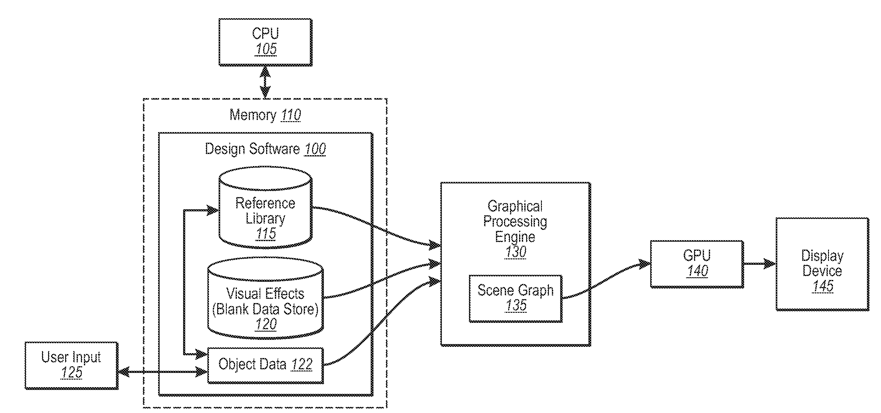
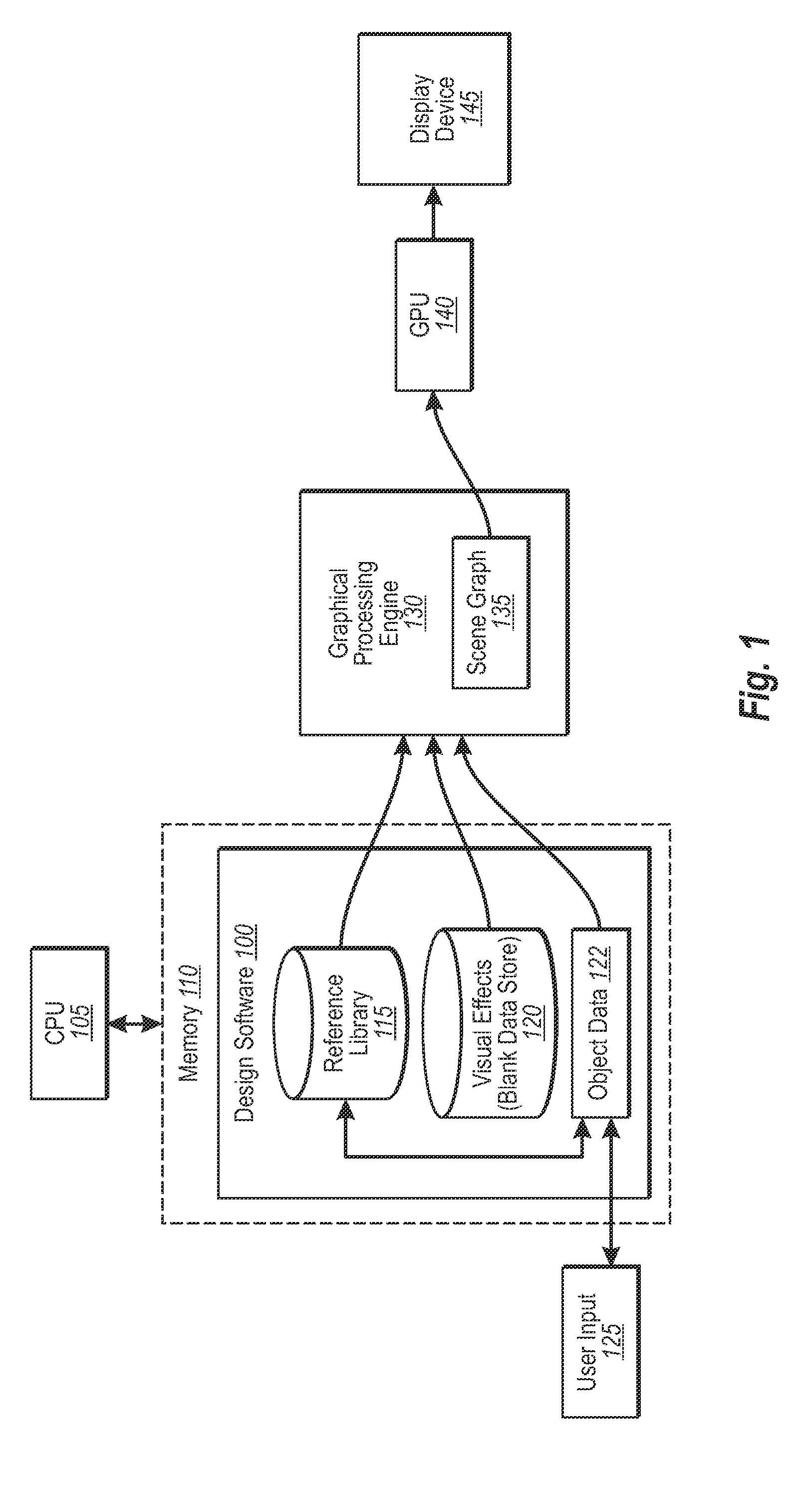
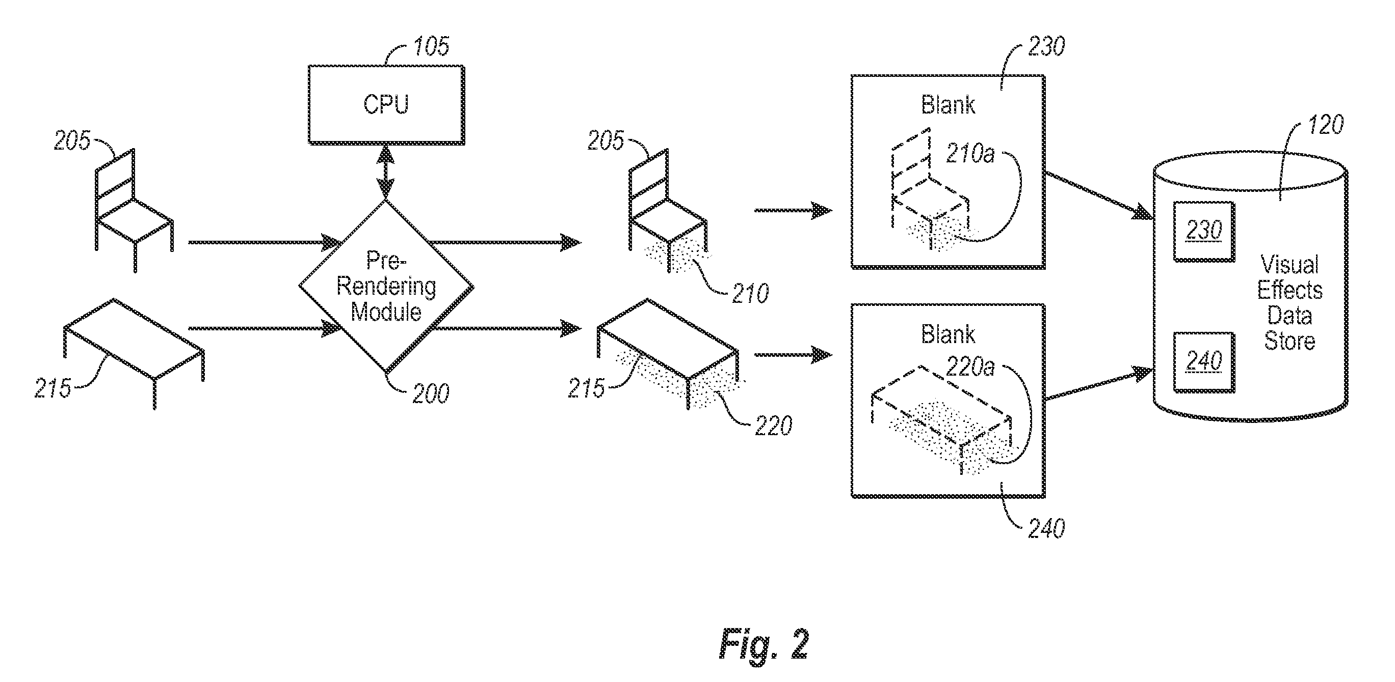
[0026]The present invention extends to systems, methods, and computer program products configured to efficiently render the visual effects for a user's design choice in a two or three-dimensional view in real-time. In particular, implementations of the present invention relate in part to prerendering lighting, shading, shadowing, or other such visual effects through a conventional central processing unit, and then later processing these effects, along with any other relevant information about the user's design choice, at a graphical processing unit during run-time.

[0027]For example, as will be understood in greater detail in the following description and claims, at least one aspect of the invention relates to front-loading the processing of much of the rendering (i.e., “prerendering”) of certain visual effects, which, in some cases can be fairly time-intensive. In particular, rendering of certain types of visual effects can be done by a central processing unit (“CPU”) at a computer,...


PUM


Abstract

Design software in accordance with an implementation of the present invention is configured to provide believable three-dimensional representations of user selections in real-time. Design elements that would otherwise be difficult to efficiently render three-dimensionally in real-time are prerendered for realistic visual effects, such as realistic shading, which correspond to various positions of the elements in a design space. Blanks of the visual effects for each position are then stored in a data store for visual effects. At run time, data associated with user design choices, as well as the blanks for any corresponding design elements are fed in one implementation to peripheral processing hardware, such as a GPU, which sends the processed data to a display device. The user is therefore able to view complex visual data of certain design choices efficiently with added realism.

Description

CROSS-REFERENCE TO RELATED APPLICATIONS[0001]The present invention claims the benefit of priority to U.S. Provisional Patent Application No. 60 / 602,233, filed on Aug. 17, 2004, entitled “Method and Apparatus for the Selection, Organization and Configuration of Products through Object Oriented Design Intent”, the entire contents of which are incorporated by reference herein.BACKGROUND OF THE INVENTION[0002]1. The Field of the Invention[0003]This invention relates to systems, methods, and computer program products for modeling, such as the design of commercial and residential interiors, and related spaces.[0004]2. Background and Relevant Art[0005]As computerized systems have increased in popularity, so has the range of applications that incorporate computational technology. Computational technology now extends across a broad range of applications, including a wide range of productivity and entertainment software. Indeed, computational technology and related software can now be found i...

Claims


Application Information

Patent Timeline
Patent Type & Authority Patents(United States)
IPC IPC(8): G06F17/50G06T15/20G06T15/50
CPCG06T15/20G06T15/50
Inventor LOBERG, BARRIE ARNOLD
Owner ARMSTRONG WORLD INDUSTRIES
Why Eureka
Try Eureka