Image encoding apparatus and image decoding apparatus

a technology of image encoding and decoding apparatus, which is applied in the direction of electrical apparatus, instruments, computing, etc., can solve the problems of reducing the encoding efficiency and the inability of conventional image encoding apparatus to carry out highly efficient encoding, and achieve the effect of high-efficiency encoding

Inactive Publication Date: 2009-07-23
MITSUBISHI ELECTRIC CORP
View PDF10 Cites 96 Cited by
  • Summary
  • Abstract
  • Description
  • Claims
  • Application Information

AI Technical Summary

Benefits of technology

[0010]It offers an advantage of being able to achieve the highly efficient encoding ev...

Problems solved by technology

However, when the correlation with the neighboring blocks is weak, the encoding efficiency is decreased.
With the foregoing configuration, the conventional image encoding...

Method used


Image

  • Image encoding apparatus and image decoding apparatus
  • Image encoding apparatus and image decoding apparatus
  • Image encoding apparatus and image decoding apparatus

Examples


embodiment 1

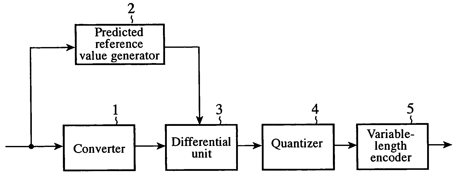
[0023]FIG. 1 is a block diagram showing a configuration of an image encoding apparatus of an embodiment 1 in accordance with the present invention. The image encoding apparatus has a converter 1, predicted reference value generator 2, differential unit 3, quantizer 4 and variable-length encoder 5.

[0024]Next, the operation will be described.

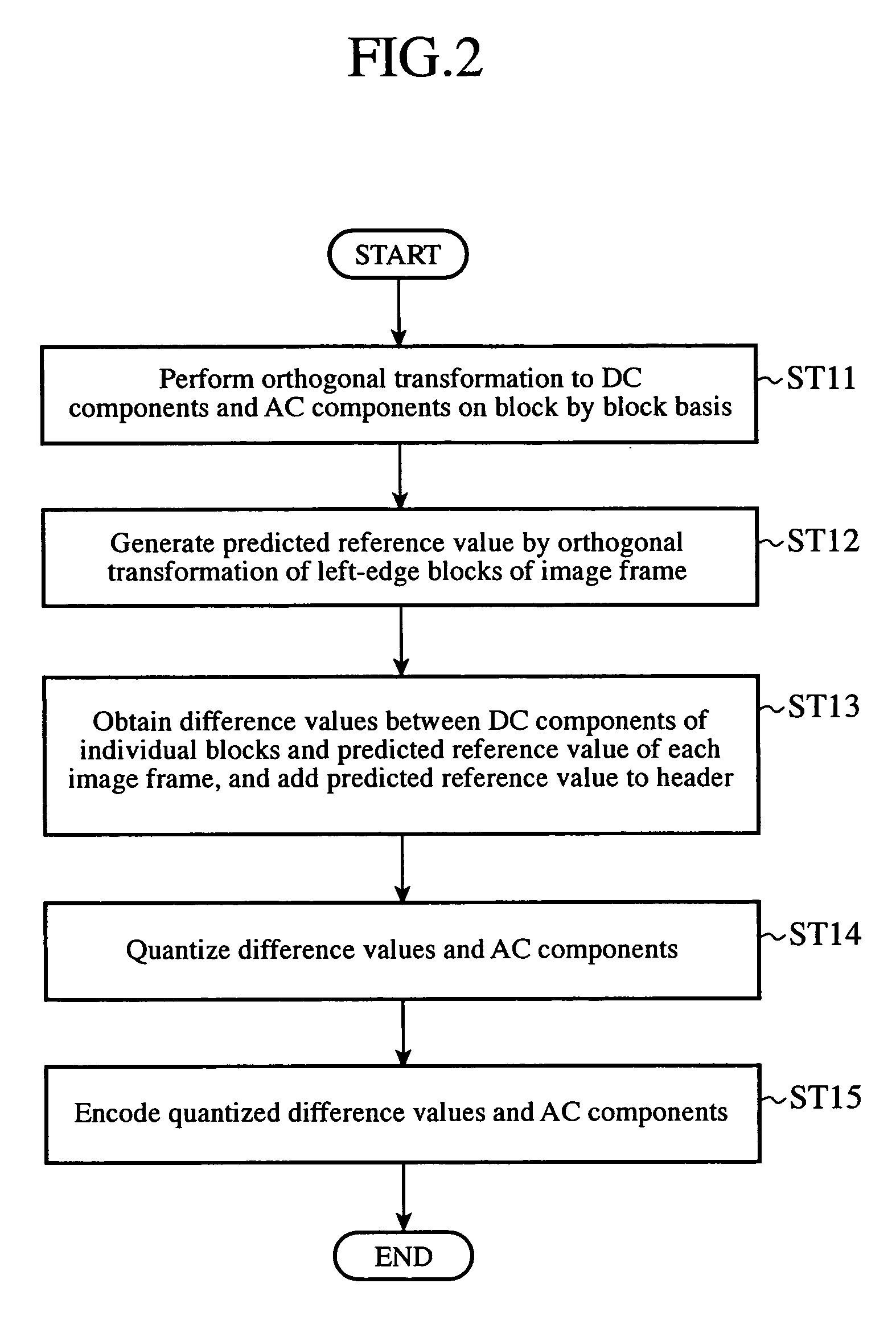
[0025]FIG. 2 is a flowchart illustrating a flow of the processing of the image encoding apparatus of the embodiment 1 in accordance with the present invention. At step ST11, the converter 1 receives an image signal of a still image or moving image, and carries out orthogonal transformation on a predetermined block by block basis, thereby converting the image signal of each block to a DC component and AC component.

[0026]At step ST12, the predicted reference value generator 2 receives the image signal, carries out the orthogonal transformation of left-edge blocks of the image frame, and obtains the average value of the DC components transformed, the...

embodiment 2

[0033]FIG. 4 is a block diagram showing a configuration of an image encoding apparatus of an embodiment 2 in accordance with the present invention. The image encoding apparatus includes a converter 1, predicted reference value generator 2, differential unit 3, quantizer 4, variable-length encoder 5 and predicted value selector 6.

[0034]Next, the operation will be described.

[0035]FIG. 5 is a flowchart illustrating a flow of the processing of the image encoding apparatus of the embodiment 2 in accordance with the present invention. At step ST21, the converter 1 receives an image signal of a still image or moving image, and carries out orthogonal transformation on a predetermined block by block basis, thereby converting the image signal of each block to a DC component and AC component.

[0036]At step ST22, the predicted reference value generator 2 receives the image signal, carries out the orthogonal transformation of left-edge blocks of the image frame, and obtains the average value of t...

embodiment 3

[0043]The block diagram showing the configuration of the image encoding apparatus of the embodiment 3 in accordance with the present invention is the same as that of FIG. 4 of the embodiment 2.

[0044]Next, the operation will be described.

[0045]Although at step ST23 of FIG. 5 in the foregoing embodiment 2, the predicted value selector 6 selects the predicted value for each predetermined block, the predicted value selector 6 in the present embodiment 3 selects the predicted value for each plurality of blocks, that is, for each macroblock consisting of four blocks, for example, and generates for each macroblock a flag indicating whether it selects the predicted reference value or the neighboring predicted value as the predicted value.

[0046]More specifically, the predicted value selector 6 calculates the sum total of the number of bits when quantizing and encoding the difference values with using the predicted reference values for all the four blocks in the macroblock, and the sum total ...


PUM


Abstract

An image encoding apparatus includes a converter 1 for receiving an image signal, and for converting the image signal of individual blocks to DC components and AC components by orthogonal transformation of the individual blocks of an image frame; a predicted reference value generator 2 for receiving the image signal, and for generating a predicted reference value of each image frame from DC components resulting from the orthogonal transformation of left-edge blocks of the image frame; and a differential unit 3 for obtaining difference values between the DC components output from the converter 1 and the predicted reference value generated by the predicted reference value generator 2. The image encoding apparatus outputs a bit stream by quantizing and variable-length encoding the AC components and difference values obtained by the differential unit 3, and by quantizing and variable-length encoding the predicted reference value to be added to a header.

Description

TECHNICAL FIELD[0001]The present invention relates to an image encoding apparatus for encoding an image signal and an image decoding apparatus for decoding an encoded image signal.BACKGROUND ART[0002]To perform highly efficient encoding of an image signal, orthogonal transformation is usually used. A conventional image encoding apparatus converts an image signal to a DC component and AC component by transforming the image signal into a frequency domain by dividing an image frame into blocks with a prescribed size of 8×8 pixels, for example, and by applying two-dimensional orthogonal transformation such as DCT (Discrete Cosine Transform) to each block divided.[0003]Then, as shown on page 106 of “MPEG”, one of General Multimedia Selected Books, compiled by The Institute of Television Engineers of Japan, and published by Ohmsha, Apr. 20, 1996, it obtains difference values between the DC component with comparatively large energy and the DC components as predicted values of neighboring b...

Claims


Application Information

Patent Timeline
IPC IPC(8): G06K9/36H04N19/50H04N1/417H04N19/102H04N19/134H04N19/136H04N19/167H04N19/176H04N19/196H04N19/60H04N19/625
CPCH04N19/50H04N19/60H04N19/48H04N19/91H04N19/593
Inventor KUDO, DAIKIYAMADA, YOSHIHISANISHIKAWA, HIROFUMIKATO, YOSHIAKI
Owner MITSUBISHI ELECTRIC CORP
Why Eureka
Try Eureka