Small footprint drilling rig

a drilling rig and small footprint technology, applied in the direction of drilling pipes, drilling/well accessories, sealing/packing, etc., can solve the problems of requiring a substantial amount of hydraulic equipment for operation, posing a safety issue, and requiring considerable time for the method

Inactive Publication Date: 2009-07-30
PROCESS MFG CORP
View PDF7 Cites 61 Cited by
  • Summary
  • Abstract
  • Description
  • Claims
  • Application Information

AI Technical Summary

Benefits of technology

[0010]In another embodiment, a substructure for a drilling apparatus is described. The substructure includes a base structure having an opening for a well head, a floor structure coupled to the base structure by a plurality of support members, a drive mechanism disposed on the floor structure, the drive mechanism providing motive force to the support members for moving the floor structure relative to the base structure in a single first direction, and a safety mechanism allowing movement of the floor structure in the first direction while preventing movement in a se...

Problems solved by technology

As such, numerous workers are required to be in the area between the drilling floor and base structure during erection, which poses a safety issue.
This method also takes considerable time, requires substantial land area for set-up and lifting (or lowering), requires permitted haul...

Method used


Image

  • Small footprint drilling rig
  • Small footprint drilling rig
  • Small footprint drilling rig

Examples


Embodiment Construction

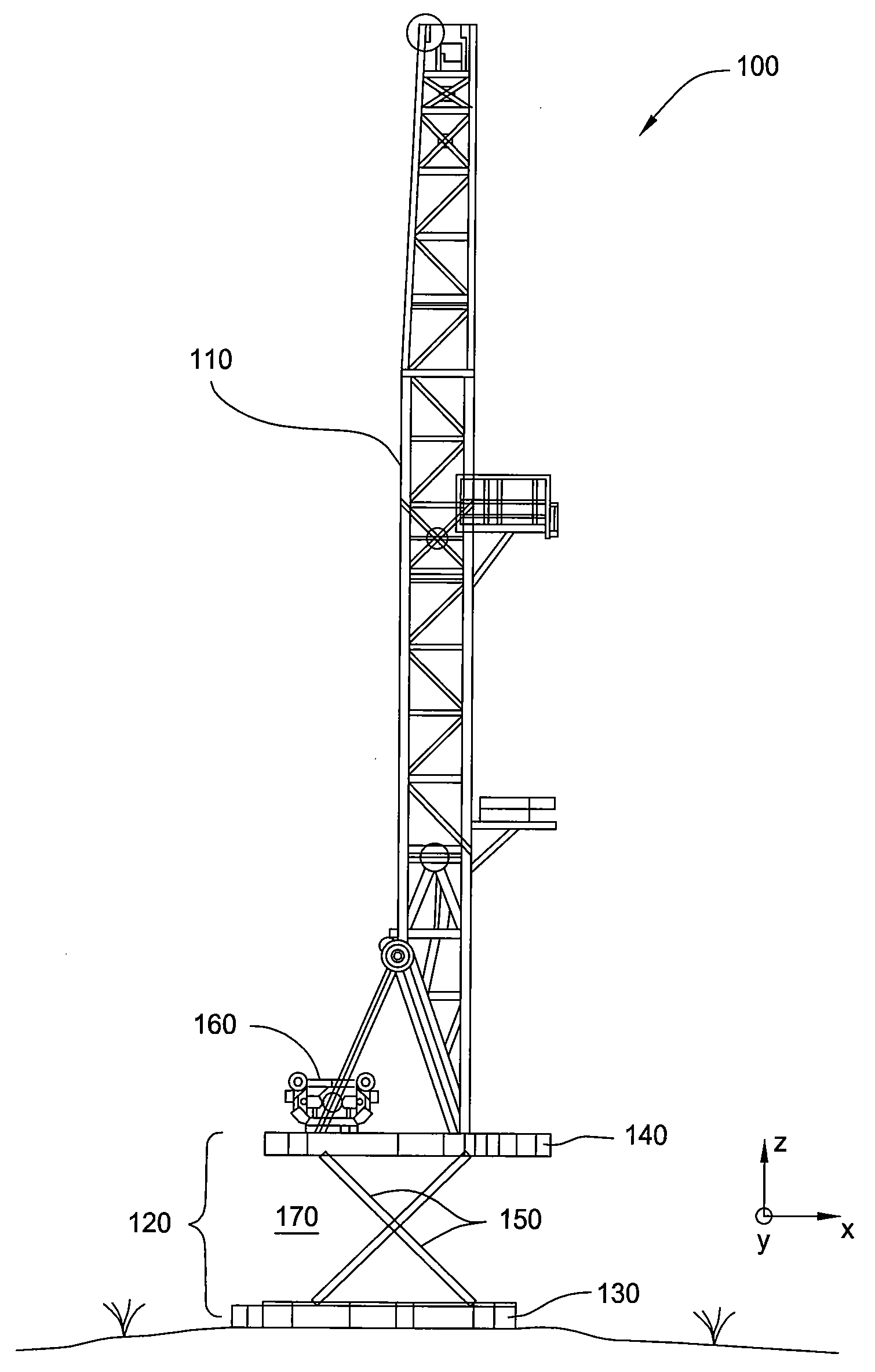
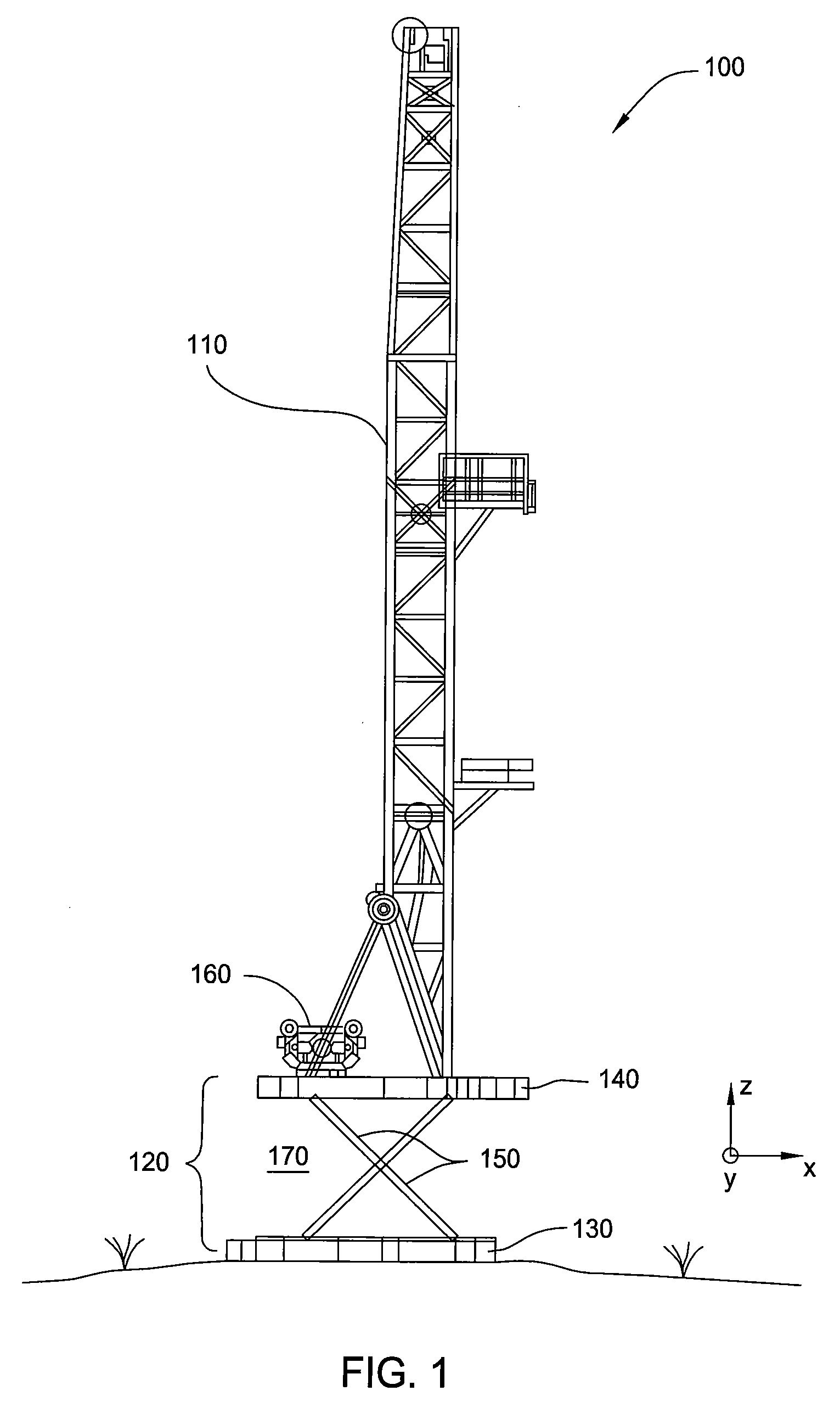
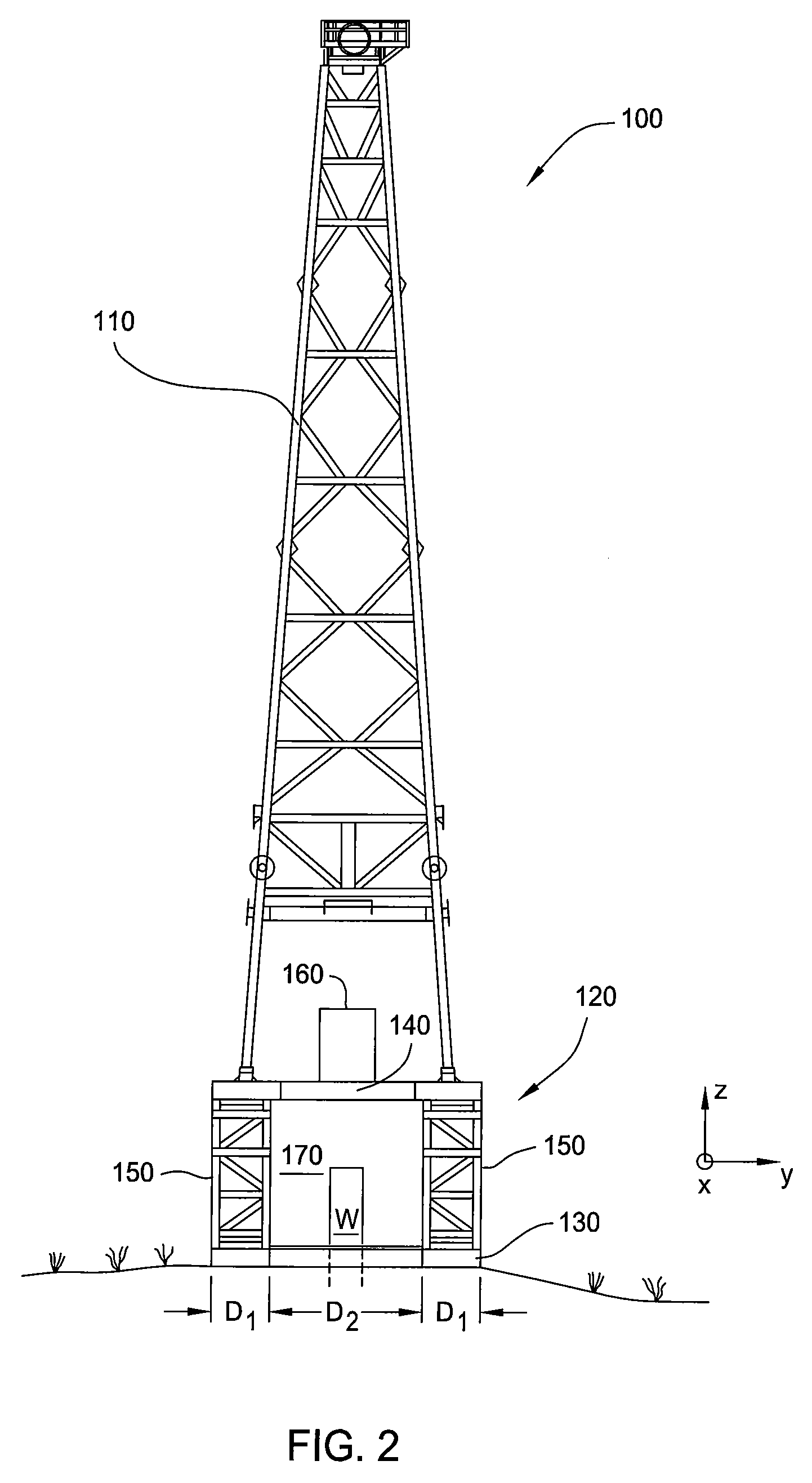
[0027]Embodiments described herein generally provide a drilling rig for use in land drilling operations having a substructure comprising base structure and a raisable drilling floor that occupies a smaller footprint and minimizes personnel during operation. Additionally, embodiments of the drilling floor and base structure described herein shorten the lifting time as compared to conventional drilling rigs, have a lessened environmental impact by minimizing hydraulic actuators, and are more cost efficient. While the embodiments described herein are exemplarily described for use with a drilling rig, some embodiments may be used for other applications requiring a floor structure to be raised or lowered relative to a base structure. Other applications include offshore platforms, work over rigs, or other application that may include lifting and lowering a floor structure relative to a base structure.

[0028]Various components described herein may be capable of independent movement in horiz...


PUM


Abstract

A method and apparatus for a moving a floor structure relative to a base structure is provided. The apparatus includes a base structure having an opening for a well head, a floor structure coupled to the base structure by a plurality of support members, and a drive mechanism disposed on the floor structure, the drive mechanism providing motive force to the support members for moving the floor structure relative to the base structure in a single first direction.

Description

CROSS-REFERENCE TO RELATED APPLICATIONS[0001]This application claims benefit of U.S. Provisional Patent Application Ser. No. 61 / 024,739, filed Jan. 30, 2008, which is incorporated herein by reference.BACKGROUND[0002]1. Field[0003]Embodiments described herein relate generally to a lifting device having a floor movable relative to a base structure. More specifically, embodiments described herein relate to a drilling rig floor vertically movable relative to a base structure.[0004]2. Description of the Related Art[0005]Conventional drilling rigs, such as land based drilling rigs, typically include a mast structure supported by a substructure having a base and a drilling floor. When the drilling rig is set-up on a location, the drilling floor typically needs to be spaced away from the base structure, for example raised relative to the base structure to provide space for equipment, such as valves, fittings, blowout preventers, and other necessary equipment, between the base structure and ...

Claims


Application Information

Patent Timeline
IPC IPC(8): E21B23/00E21B7/02
CPCE21B15/00E21B7/02
Inventor DITTA, JOSEPH WILLIAMGONZALEZ, REYNALDO A.REIDER, ROBERT GARY
Owner PROCESS MFG CORP
Why Eureka
Try Eureka