
Energy Storage System and Method of Charging

Active Publication Date: 2009-07-30
ENERGIZER BRANDS
View PDF26 Cites 5 Cited by
  • Summary
  • Abstract
  • Description
  • Claims
  • Application Information

AI Technical Summary

Benefits of technology

[0006]In accordance with one aspect of the present invention, an energy storage system is provided that includes a plurality of battery cells and a controller. The plurality of battery cells include a first battery cell and a second battery cell. The controller is in communication with the first and second battery cells, which controls an electrical current supplied to the first and second battery cells. The controller controls the electrical current such that a first charging method is utilized when a voltage potential of the first and second battery cells is less than a f

Problems solved by technology

Typically, when the flashlight is connected to the stationary external power supply, the flashlight can continue to illuminate light, but the mobility of the flashlight is now hindered.
When the flashlight is not directly connected to the AC wall outlet, such as by an extension cord, the flashlight has limited mobility.

Method used


Image

  • Energy Storage System and Method of Charging
  • Energy Storage System and Method of Charging
  • Energy Storage System and Method of Charging

Examples


Embodiment Construction

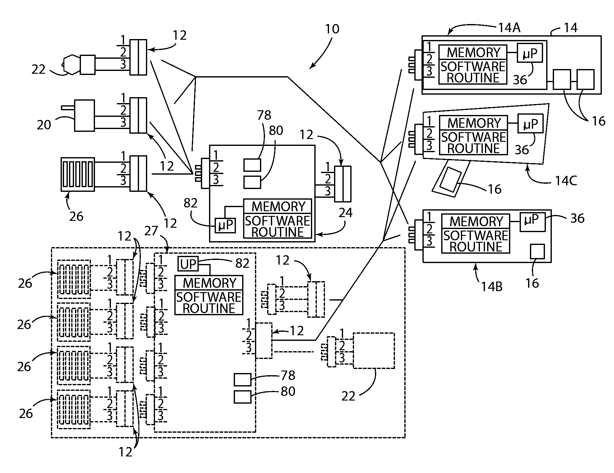
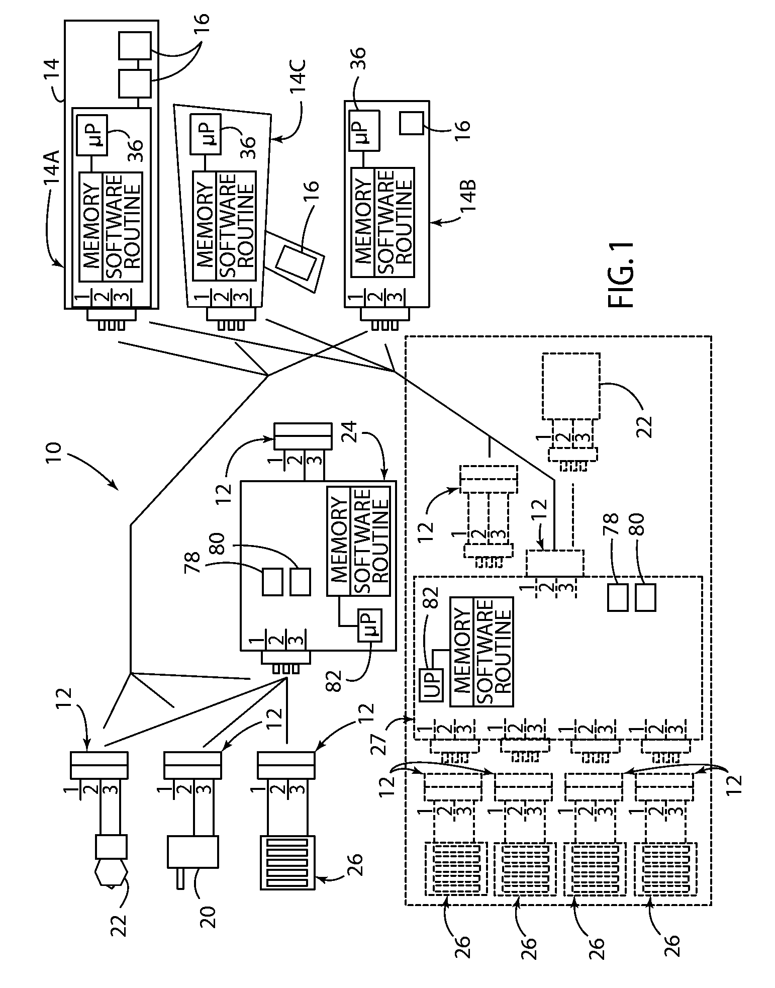
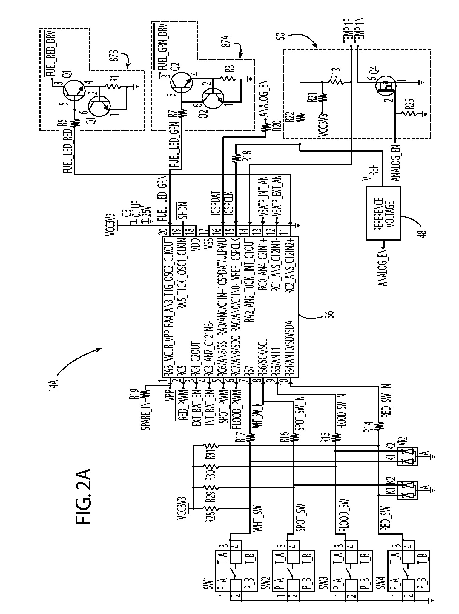
[0046]Before describing in detail embodiments that are in accordance with the present invention, it should be observed that the embodiments include combinations of method steps and apparatus components related to a lighting system and method of operating thereof. Accordingly, the apparatus components and method steps have been represented, where appropriate, by conventional symbols in the drawings, showing only those specific details that are pertinent to understanding the embodiments of the present invention so as not to obscure the disclosure with details that will be readily apparent to those of ordinary skill in the art having the benefit of the description herein. Further, like reference characters in the description and drawings represent like elements.

[0047]In this document, relational terms, such as first and second, top and bottom, and the like, may be used to distinguish one entity or action from another entity or action, without necessarily requiring or implying any actua...


PUM


Abstract

A lighting system is provided that includes at least one lighting device, at least one connector, and a plurality of external power sources. The external power sources are adapted to be electrically connected to the lighting device by the connector. One of the external power sources is an energy storage system having a plurality of battery cells. A first charging method is utilized when a voltage potential of first and second battery cells is less than a voltage potential threshold, a second charging method is utilized when the voltage potential of the first and second battery cells is equal to or greater than the voltage potential threshold, and the first charging method is utilized to charge the first battery cell prior to charging the second battery cell when the first battery cell voltage potential is below the voltage potential threshold and greater than the second battery cell voltage potential.

Description

CROSS-REFERENCE TO RELATED APPLICATIONS[0001]This application claims the benefit under 35 U.S.C. §119(e) of U.S. Provisional Patent Application No. 61 / 023,632, filed on Jan. 25, 2008, the entire disclosure of which is hereby incorporated herein by reference.FIELD OF THE INVENTION[0002]The present invention generally relates to an energy storage system and method of charging, and more particularly, to an energy storage system having a plurality of battery cells and a method of charging the plurality of battery cells.BACKGROUND OF THE INVENTION[0003]Generally, a mobile lighting device, such as a flashlight, is powered by a power source that is internal to the flashlight, such as a battery. Typically, the batteries of the flashlight device can be replaced when the state of charge of the batteries is below an adequate state of charge for providing electrical power for the light source of the flashlight. Since the flashlight is being powered by batteries, the flashlight can generally emi...

Claims


Application Information

Patent Timeline
IPC IPC(8): H02J7/00H05B44/00
CPCF21L4/02F21V5/006F21V23/0414F21W2111/10F21Y2101/02F21V29/76H05B33/0803H05B33/0845H05B37/02F21V5/007F21V29/75F21Y2113/00F21Y2115/10H05B45/10H05B47/10H05B45/18H05B45/3725H05B45/32H05B45/56
Inventor CRAWFORD, JOHN D.HOFFMAN, PETER F.SPARTANO, DAVID A.HUANG, FRANK F.
Owner ENERGIZER BRANDS
Learn More