Power supply circuit for flash discharge tube

Inactive Publication Date: 2006-07-25
HAMAMATSU PHOTONICS KK
View PDF15 Cites 0 Cited by
  • Summary
  • Abstract
  • Description
  • Claims
  • Application Information

AI Technical Summary

Benefits of technology

[0012]When the charge and discharge capacitor is charged through the transformer, a part of the surge current at the time when the surge current occurs may flow into the transformer, so that the transformer may generate heat or be damaged by flow of large current thereto. By providing only the switching element and connecting the transformer and the charge and discharge capacitor to each other only during the charge of the charge and discharge capacitor,

Problems solved by technology

In connection with this, the energy accumulated in the residual inductance is increased and the surge current is also increased to a large current of 100 amperes, so that there occurs a problem that the surge current dio

Method used


Image

  • Power supply circuit for flash discharge tube
  • Power supply circuit for flash discharge tube
  • Power supply circuit for flash discharge tube

Examples


first embodiment

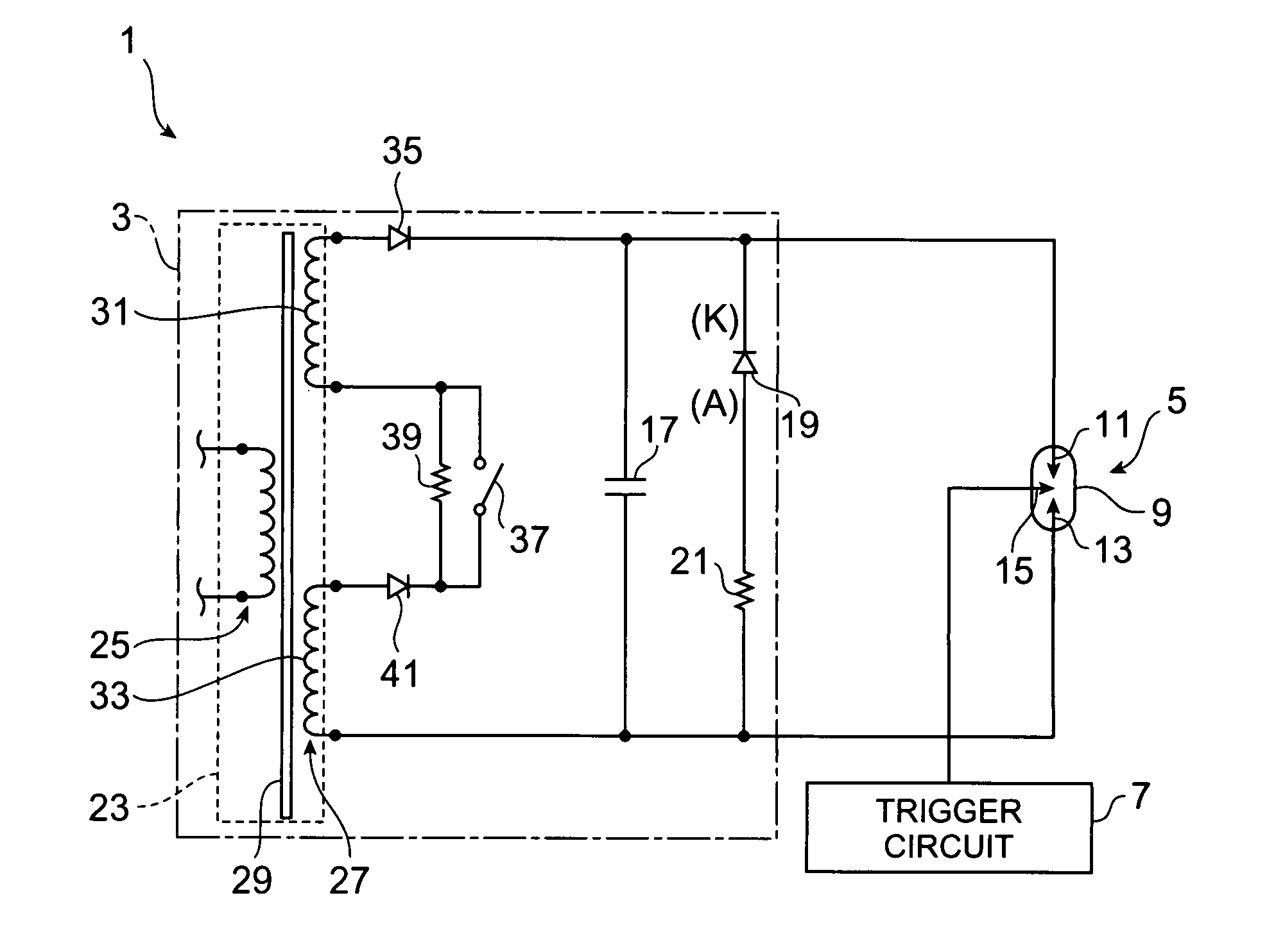
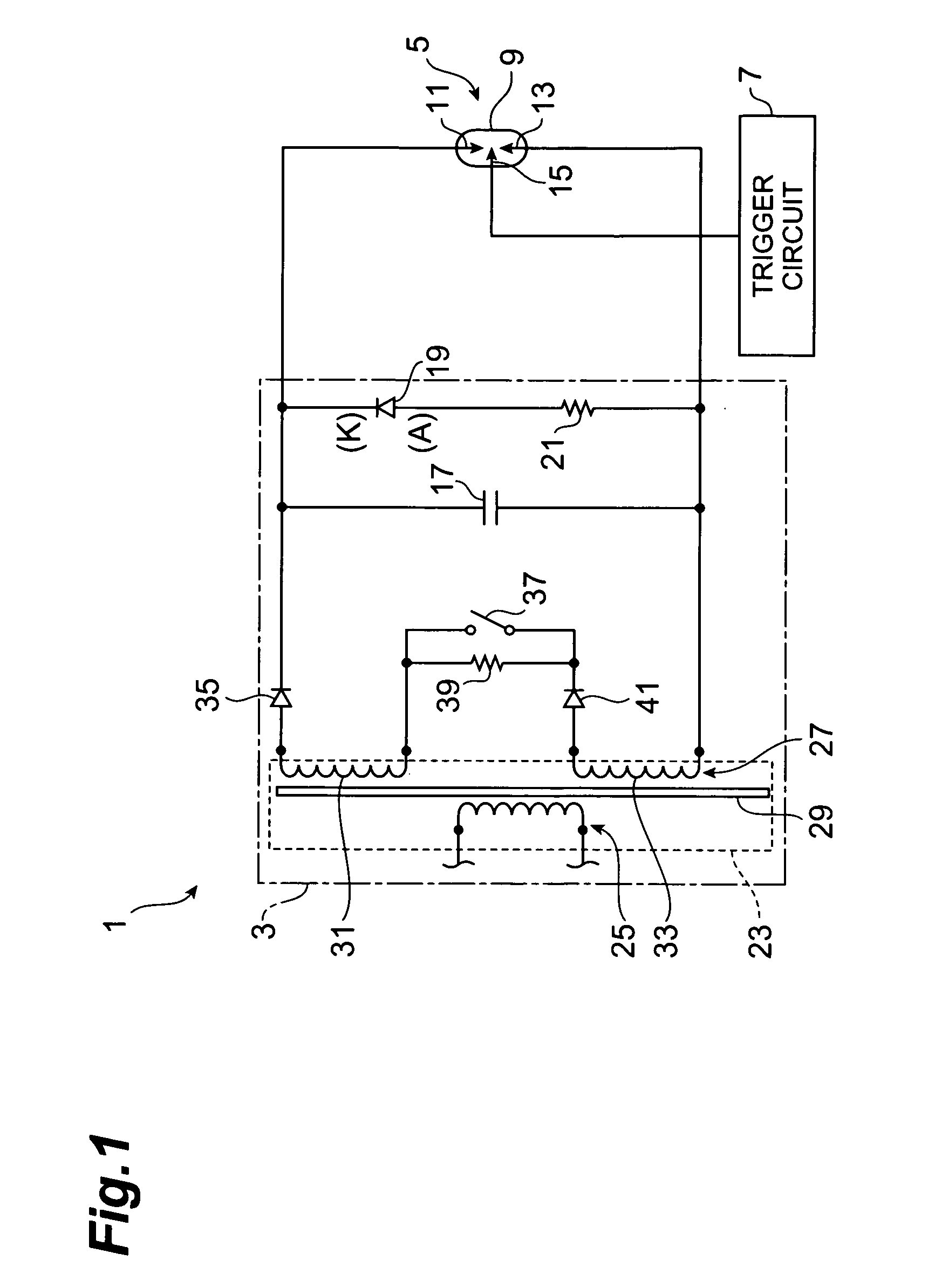
[0019]FIG. 1 is a circuit diagram showing the construction of a flash discharge tube apparatus 1 containing a power supply circuit for a flash discharge tube according to the present invention. The flash discharge tube apparatus 1 comprises of a power supply circuit 3 for a flash discharge tube of this embodiment, a flash discharge tube 5 and a light emission trigger circuit 7. The flash discharge tube 5 is a gas discharge tube in which rare gas is filled, and, for example, it is a xenon flash lamp. The flash discharge tube 5 has a cylindrical type glass container 9, and a positive electrode 11, a cathode 13 and a trigger electrode 15 which are disposed in the container 9. Xenon gas is filled in the glass container 9.

[0020]The trigger electrode 15 of the flash discharge tube 5 is connected to the light emission trigger circuit 7. A trigger voltage when the flash discharge tube 5 is made to emit light by the light emission trigger circuit 7 is applied to the trigger electrode 15.

[002...

second embodiment

[0043]Next, another embodiment of the present invention will be described. FIG. 5 is a circuit diagram showing the construction of a flash discharge tube apparatus including the power supply circuit for the flash discharge tube according to the present invention. The difference of the power supply circuit 3A for the flash discharge tube of FIG. 5 from the power supply circuit 3 for the flash discharge tube of FIG. 1 is that the rectifier diode 35 is connected to the charge and discharge capacitor 17, the cathode of the surge current diode 19 and the positive electrode 11 of the flash discharge tube 5 through the switching element 37 and the transformer protecting resistor 39 which are connected to each other in parallel, and the first coil portion 31 and the second coil portion 33 are connected to each other in series through the rectifying capacitor 41. That is, the parallel connection circuit of the switching element 37 and the transformer protecting resistor 39 is disposed at the...

third embodiment

[0044]FIG. 6 is a circuit diagram showing the construction of a flash discharge tube apparatus including the power supply circuit for the flash discharge tube according to the present invention. The difference of the power supply circuit 3B for the flash discharge tube of FIG. 6 from the power supply circuit 3 for the flash discharge tube of FIG. 1 is that the second coil portion 33 is connected to the charge and discharge capacitor 17, the diode protecting resistor 21 and the cathode 13 of the flash discharge tube 5 through the switching element 37 and the transformer protecting resistor 39 which are connected to each other in parallel, and the first coil portion 31 and the second coil portion 33 are connected to each other in series through the rectifying capacitor 41. That is, the parallel connection circuit of the switching element 37 and the resistor 39 is disposed at the low voltage side of the transformer 23.

[0045]Furthermore, the secondary coil 27 is not limited to the two-s...


PUM


Abstract

A voltage is applied across the positive electrode and negative electrode of a flash discharge tube (xenon flash lamp) to emit light by a charge and discharge capacitor. This voltage application accumulates energy in a residual inductance existing in the circuit constructed by the flash discharge tube and the power supply circuit for the flash discharge tube. This energy is made to flow as surge current into a series circuit comprising the flash discharge tube, a surge current diode and a diode protecting resistor.

Description

RELATED APPLICATIONS[0001]This is a Continuation-In-Part application of International Patent Application serial No. PCT / JP02 / 11300 filed on 30 Oct., 2002 now pending.BACKGROUND OF THE INVENTION[0002]1. Field of the Invention[0003]The present invention relates to a power supply circuit for a flash discharge tube used to make a flash discharge tube such as a xenon flash lamp emit light.[0004]2. Related Background Art[0005]A flash discharge tube represented by a xenon flash lamp is widely used as a light source for spectroscopic analysis, a light source for a flash lamp of a camera, a lamp for a high-speed shutter camera or the like because the spectral characteristics of the output light thereof are approximate to sunlight and it can provide stable flash light having a very short light-emission duration. Rare gas such as xenon or the like is filled in such a flash discharge tube. By applying high-voltage pulse current to a trigger electrode disposed in the discharge tube, electrical b...

Claims


Application Information

Patent Timeline
IPC IPC(8): H05B37/00G03B15/03G03B15/05H05B41/32H05B41/34
CPCH05B41/34
Inventor MAISHIMA, MITSUYOSHI
Owner HAMAMATSU PHOTONICS KK
Why Eureka
Try Eureka