SILICON-BASED SEMICONDUCTOR DEVICE COMPRISING eFUSES FORMED BY AN EMBEDDED SEMICONDUCTOR ALLOY

a technology of semiconductor fuses and alloys, which is applied in the manufacture of emergency protective devices, heat/cooling contact switches, information storage, etc., can solve the problems of increased power consumption, increased complexity, and increased complexity of circuits, so as to reduce the amount of metal silicide materials, reduce currents, and improve the reliability of programming processes.

Inactive Publication Date: 2011-06-30
GLOBALFOUNDRIES INC
View PDF15 Cites 18 Cited by
  • Summary
  • Abstract
  • Description
  • Claims
  • Application Information

AI Technical Summary

Benefits of technology

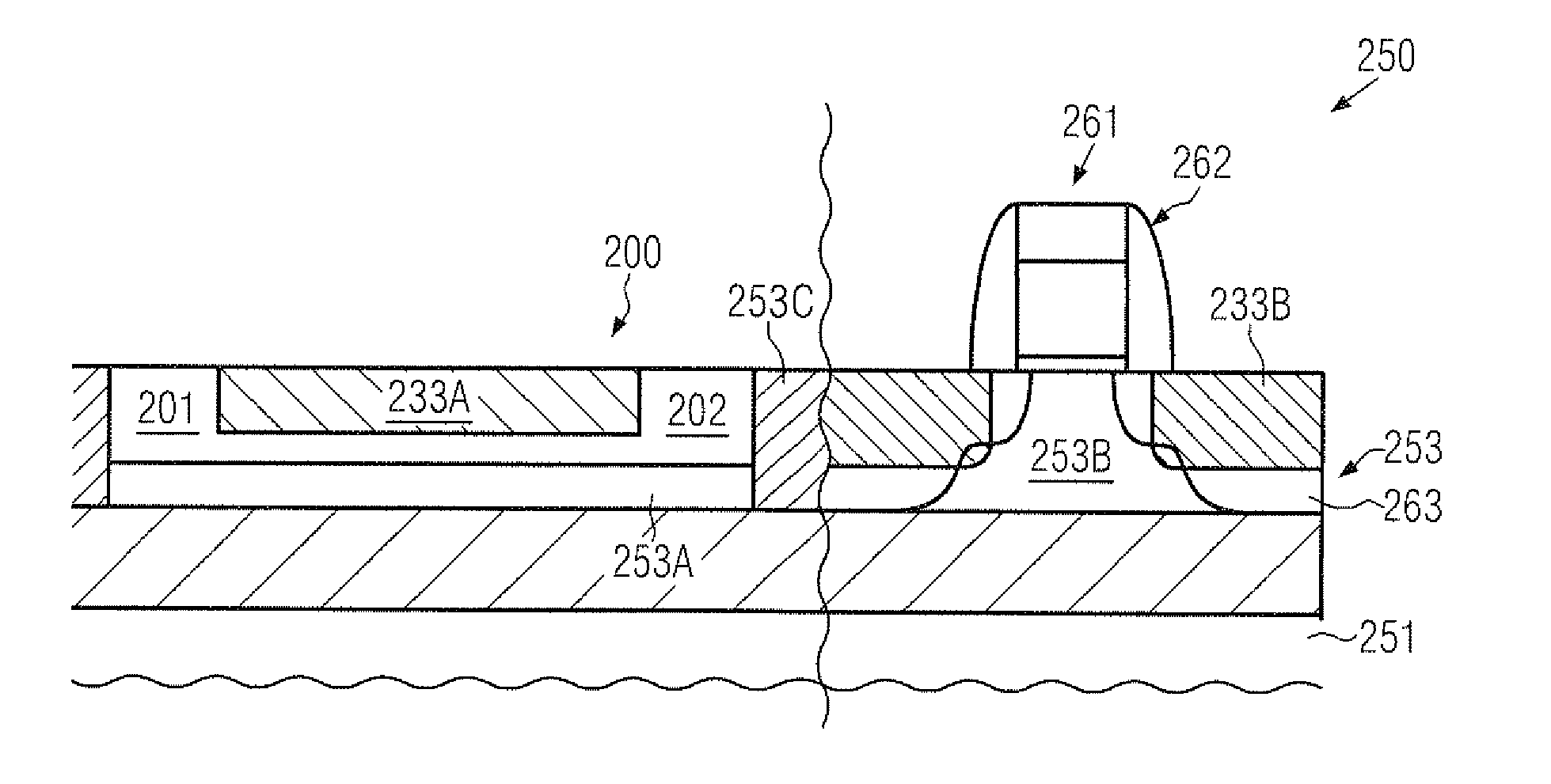
[0018]Generally, the present disclosure provides semiconductor devices and methods for forming the same, in which the electronic fuses may be provided so as to enable the programming of electronic fuses with reduced currents without negatively affecting the reliability of the programming process. To this end, the amount of metal silicide material may be reduced, at least in the fuse body of an electronic fuse, so that a higher current density, in combination with an increased resistivity, may be achieved in the metal silicide material for a given desired magnitude of current. In some illustrative aspects disclosed herein, a reduced amount of metal silicide, for instance a reduced thickness of a metal silicide layer in the fuse body, possibly in combination with a reduced thickness in the contact areas, may be achieved by replacing a portion of the initial silicon-based semiconductor material with a semiconductor material having a reduced silicidation rate, thereby reducing the degree of interdiffusion during the silicidation process. Consequently, the resulting metal silicide material may have a reduced thickness, which in turn may lead to a more pronounced electromigration effect for a given amount of current. Hence, corresponding peripheral components, such as transistors for supplying the voltage and current for the programming of the electronic fuses, may be reduced in size, which in turn may allow a generally increased packing density of complex semiconductor devices.

Problems solved by technology

For this reason, highly complex circuits have been developed, which may include different types of circuits, such as analog circuits, digital circuits and the like, thereby providing entire systems on a single chip (SoC).
However, the shrinkage of the gate dielectric thickness may be associated with an exponential increase of the leakage currents, which may directly tunnel through the thin gate dielectric material, thereby contributing to enhanced power consumption and thus waste heat, which may contribute to sophisticated conditions during operation of the semiconductor device.
Moreover, charge carriers may be injected into the gate dielectric material and may also contribute to a significant degradation of transistor characteristics, such as threshold voltage of the transistors, thereby also contributing to variability of the transistor characteristics over the lifetime of the product.
Consequently, the combination of the various circuit portions in a single semiconductor device may result in a significant different behavior with respect to performance and reliability, wherein the variations of the overall manufacturing process flow may also contribute to a further discrepancy between the various circuit portions.
However, with the continuous shrinkage of critical device dimensions in sophisticated semiconductor devices, the reliability of the programming of corresponding electronic fuses may require tightly set margins for the corresponding voltages used to program the electronic fuses, which may not be compatible with the overall specifications of the semiconductor devices or may at least have a severe influence on the flexibility of operating the device.
Frequently, providing the fuses on the basis of a configuration as used for gate electrodes may not be compatible with the requirements to be met by the fuses.
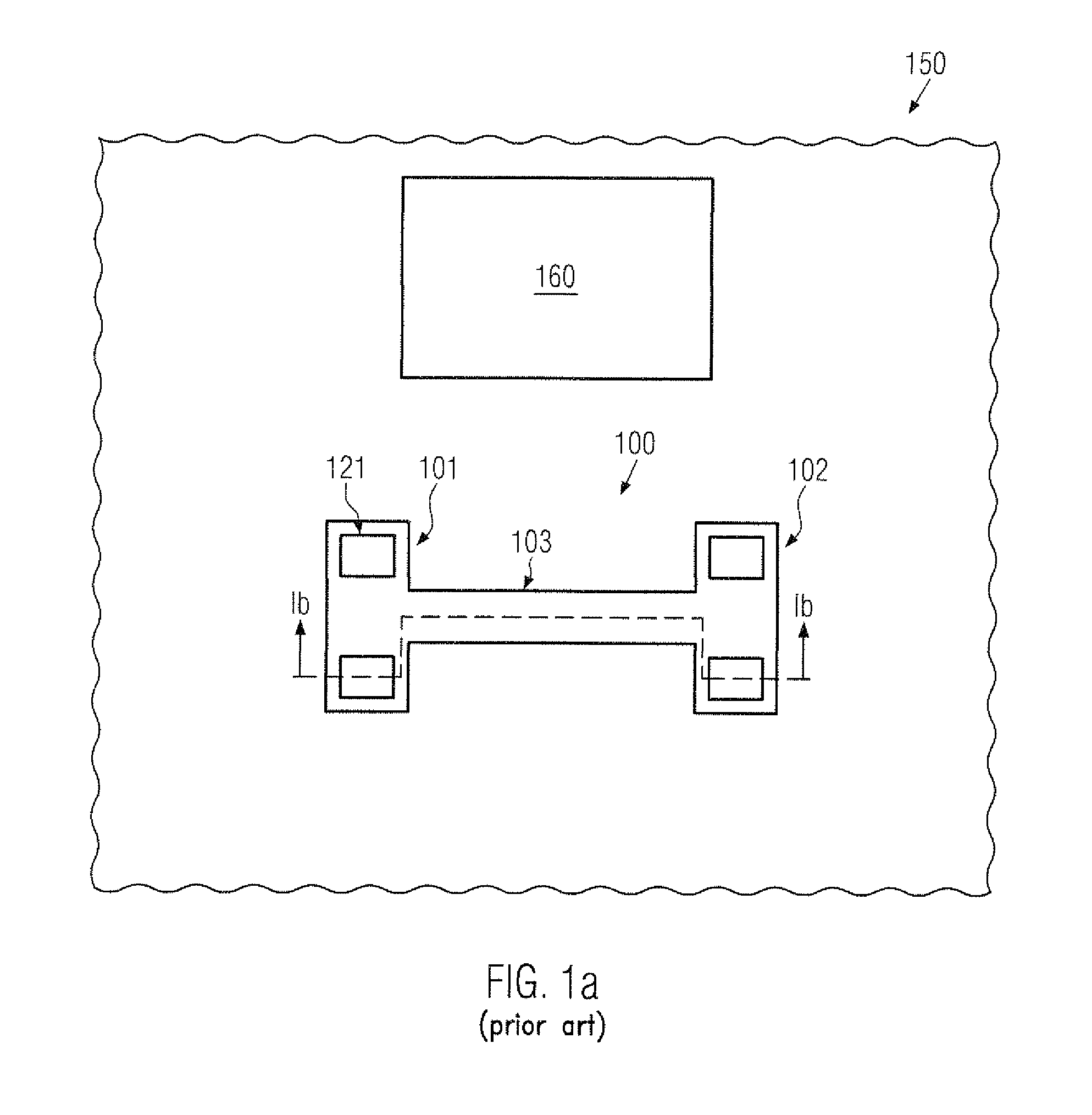
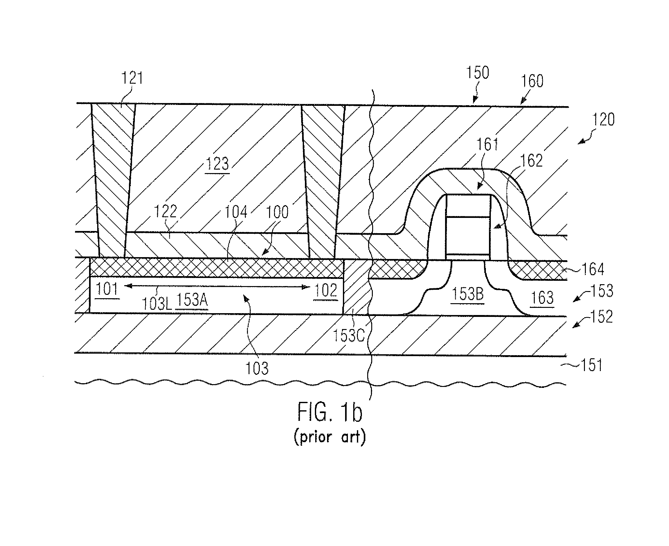
Thus, any irregularity upon forming the electronic fuse 100 and / or the contact elements 121 may result in a significant variation of the required voltage values and current densities for programming the electronic fuse 100, which may not be compatible with the tightly set process tolerances in sophisticated semiconductor devices.

Method used


Image

  • SILICON-BASED SEMICONDUCTOR DEVICE COMPRISING eFUSES FORMED BY AN EMBEDDED SEMICONDUCTOR ALLOY
  • SILICON-BASED SEMICONDUCTOR DEVICE COMPRISING eFUSES FORMED BY AN EMBEDDED SEMICONDUCTOR ALLOY
  • SILICON-BASED SEMICONDUCTOR DEVICE COMPRISING eFUSES FORMED BY AN EMBEDDED SEMICONDUCTOR ALLOY

Examples


Embodiment Construction

[0031]Various illustrative embodiments of the invention are described below. In the interest of clarity, not all features of an actual implementation are described in this specification. It will of course be appreciated that in the development of any such actual embodiment, numerous implementation-specific decisions must be made to achieve the developers' specific goals, such as compliance with system-related and business-related constraints, which will vary from one implementation to another. Moreover, it will be appreciated that such a development effort might be complex and time-consuming, but would nevertheless be a routine undertaking for those of ordinary skill in the art having the benefit of this disclosure.

[0032]The present subject matter will now be described with reference to the attached figures. Various structures, systems and devices are schematically depicted in the drawings for purposes of explanation only and so as to not obscure the present disclosure with details ...


PUM

PropertyMeasurementUnit
sizesaaaaaaaaaa
gate lengthaaaaaaaaaa
lengthaaaaaaaaaa

Abstract

An electronic fuse may receive a silicon/germanium material in the fuse body, which in turn may result in the formation of a metal silicide material of reduced thickness. Consequently, the current density and, thus, the electromigration and heat generation in the metal silicide material may be increased for a given amount of current. Consequently, transistor switches for applying the programming pulse to the electronic fuse may be reduced in size.

Description

BACKGROUND OF THE INVENTION[0001]1. Field of the Invention[0002]The present disclosure generally relates to the field of fabricating integrated circuits, and, more particularly, to forming electronic fuses for providing device internal programming capabilities in complex integrated circuits.[0003]2. Description of the Related Art[0004]In modern integrated circuits, a very high number of individual circuit elements, such as field effect transistors in the form of CMOS, NMOS, PMOS elements, resistors, capacitors and the like are formed on a single chip area. Typically, feature sizes of these circuit elements are steadily decreasing with the introduction of every new circuit generation, to provide currently available integrated circuits with an improved degree of performance in terms of speed and / or power consumption. A reduction in size of transistors is an important aspect in steadily improving device performance of complex integrated circuits, such as CPUs. The reduction in size is ...

Claims


Application Information

Patent Timeline
Patent Type & Authority Applications(United States)
IPC IPC(8): H01H37/76H01H69/02
CPCG11C17/16H01L21/823807H01L23/5256Y10T29/49107H01L29/7833H01L29/7848H01L2924/3011H01L27/0629H01L2924/0002H01L2924/00
Inventor KURZ, ANDREASKRONHOLZ, STEPHANBOSCHKE, ROMAN
Owner GLOBALFOUNDRIES INC
Why Eureka
Try Eureka