Adaptive circuit

Active Publication Date: 2013-02-28
KONINKLIJKE PHILIPS ELECTRONICS NV
View PDF2 Cites 21 Cited by
  • Summary
  • Abstract
  • Description
  • Claims
  • Application Information

AI Technical Summary

Benefits of technology

[0032]When the active switch is realised using a transistor, the switch will be closed, i.e. conducting, whenever the base or gate voltage exceeds a certain level, and the switch is effectively controlled with a discrete drive signal that can be generated using an appropriate Zener diode. The active switch could however be realised using an alternative to the discrete Zener voltage source described above. Therefore, in another preferred embodiment of the invention, the active switch is actuated by a continuous drive signal. For example, with suitable circuitry between a transistor for meas

Problems solved by technology

However, there are some drawbacks related to direct mains driving.
Hence, the ACLEDs are driven with a reduced efficiency due to ‘droop’.
Secondly, current flow through the ACLED package is only possible when the instantaneous mains voltage is higher than the forward voltage of the package's LED string.
This is perceived as an annoying ‘flicker’, so that such lamps are unacceptable for applications such as indoor lighting.
Evidently, the more junctions of a given size are connected in series to act as an LED load, the higher will be the power consumption of the LED load.
However, very small junctions are expensive to manufacture, and, because of the smaller active area, the overall efficien

Method used


Image

  • Adaptive circuit
  • Adaptive circuit
  • Adaptive circuit

Examples


Embodiment Construction

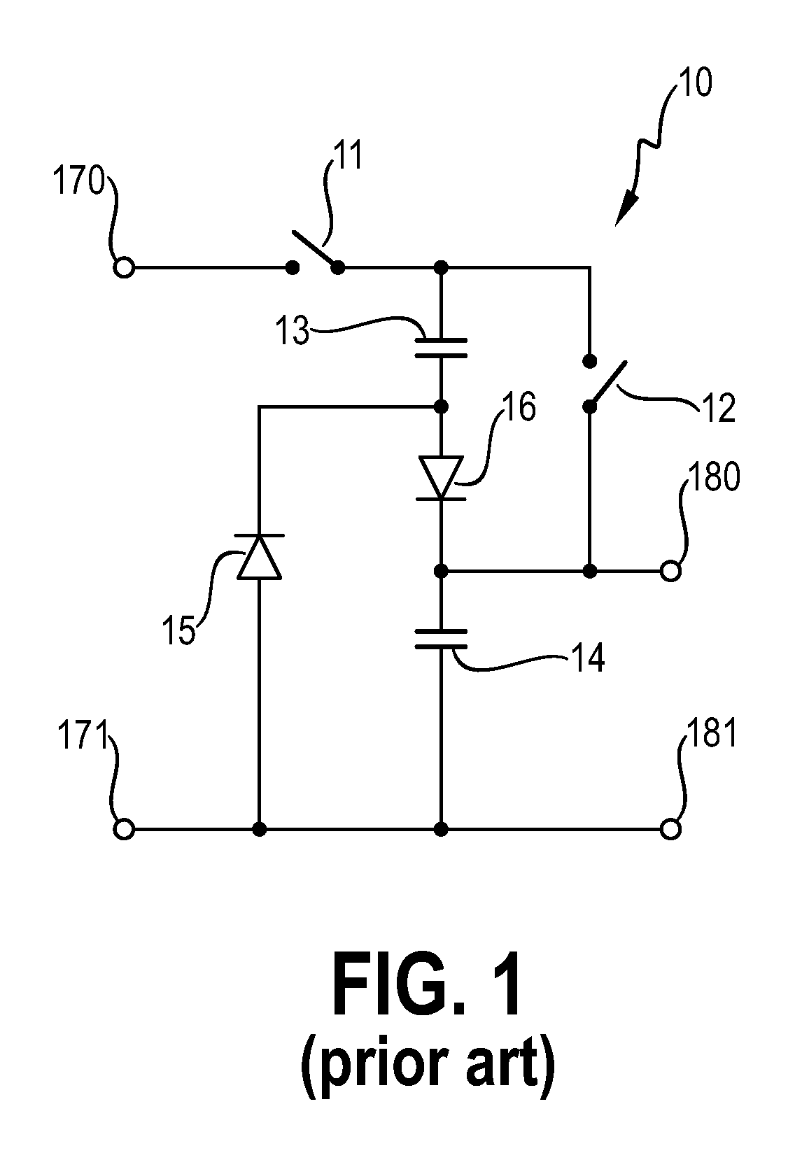
[0041]FIG. 1 shows a prior art adaptive circuit 10 of the type described in

[0042]JP 5709736 for stepping down an input voltage applied across input terminals 170, 171 in order to obtain a lower voltage for a load connected across output terminals 180, 181. This type of circuit is suited for small device applications such as hand-held devices, where a transformer would be unsuitable owing to its size and weight. The input voltage can be a DC voltage or a rectified AC voltage. A first switch 11, a first capacitor 13, a diode 16 and a second capacitor 14 are connected in series. A second diode 15 is connected in parallel with the first diode 16 and the second capacitor 14. A second switch 12 is connected across the first capacitor 13 and first diode 16. To step down the input voltage, the first and second switches 11, 12 are switched alternately. When the first switch 11 is closed (and the second switch 12 is open), the series-connected capacitors 13, 14 are charged and the load is dri...


PUM


Abstract

The invention describes an adaptive circuit (1, 1′) for driving a lower-voltage DC load (2) from a rectified higher-voltage AC supply (3), which adaptive circuit (1, 1′) comprises a charge-storage circuit (21, 21′), which charge storage circuit (21, 21′) comprises a first capacitor (C1) and a second capacitor (C2) connected essentially in series, wherein the second capacitor (C2) is connected at least in parallel with the load (2); and an active switch (22, 22′) realised as a controlled current source (22, 22′) for controlling a load current (Iload) through the load (2) such that, in a closed switch state, load current (Iload) is drawn essentially from the first capacitor (C1) of the charge-storage circuit (21, 21′), and, during an open switch state, load current (Iload) is drawn essentially from the second capacitor (C2). The invention also describes an LED retrofit lamp (4) comprising a connecting means (40) for connecting the lamp (4) to a higher-voltage mains supply signal (U PS); an LED device (2) rated for a lower-voltage supply; and such an adaptive circuit (1, 1′) for adapting the higher-voltage mains supply signal (U PS) to a low-voltage signal (U C2) for driving the lower-voltage LED device (2). The invention also describes a method of driving a lower-voltage DC load (2) from a rectified higher-voltage AC supply (3).

Description

FIELD OF THE INVENTION[0001]The invention describes an adaptive circuit for driving a lower-voltage DC load from a higher-voltage AC supply. The invention also describes an LED retrofit lamp and a method of driving a lower-voltage DC load from a higher-voltage AC supply.BACKGROUND OF THE INVENTION[0002]Advances in LED (light-emitting diode) technology have led to the development of LEDs with a satisfactorily high light output, making them an interesting alternative to incandescent or fluorescent lamps. An LED lighting device can easily be designed to exceed an efficacy of 100 μm / W. Furthermore, LEDs are more efficient and more reliable than conventional lamps, and have a longer lifetime. Therefore, using LEDs to replace conventional lamps contributes to a reduction in energy consumption and reduced emissions from power plants. Packages or chips containing series-connected LED junctions (to form an LED string with a high forward voltage) are suitable for low-cost general lighting app...

Claims


Application Information

Patent Timeline
IPC IPC(8): H02M7/06H05B37/00H05B44/00
CPCH02M1/08H02M3/156H05B33/0884H05B33/0824H05B33/08H05B33/0815H02M3/07H05B45/37H05B47/10H02M7/05Y02B20/30Y02B20/40H05B45/44H05B45/54
Inventor RADERMACHER, HARALD
Owner KONINKLIJKE PHILIPS ELECTRONICS NV
Why Eureka
Try Eureka