Battery charging apparatus and battery charging method

Active Publication Date: 2019-05-02
LITE ON ELECTRONICS (GUANGZHOU) LTD +1
View PDF2 Cites 2 Cited by
  • Summary
  • Abstract
  • Description
  • Claims
  • Application Information

AI Technical Summary

Benefits of technology

[0004]The present disclosure is directed to a battery charging apparatus and a battery charging method which are capab

Problems solved by technology

On one hand, using the dedicated HV for charging HV battery system may suffer f

Method used


Image

  • Battery charging apparatus and battery charging method
  • Battery charging apparatus and battery charging method
  • Battery charging apparatus and battery charging method

Examples


Example

[0022]Reference will now be made in detail to the present preferred embodiments of the disclosure, examples of which are illustrated in the accompanying drawings. Wherever possible, the same reference numbers are used in the drawings and the description to refer to the same or like parts.

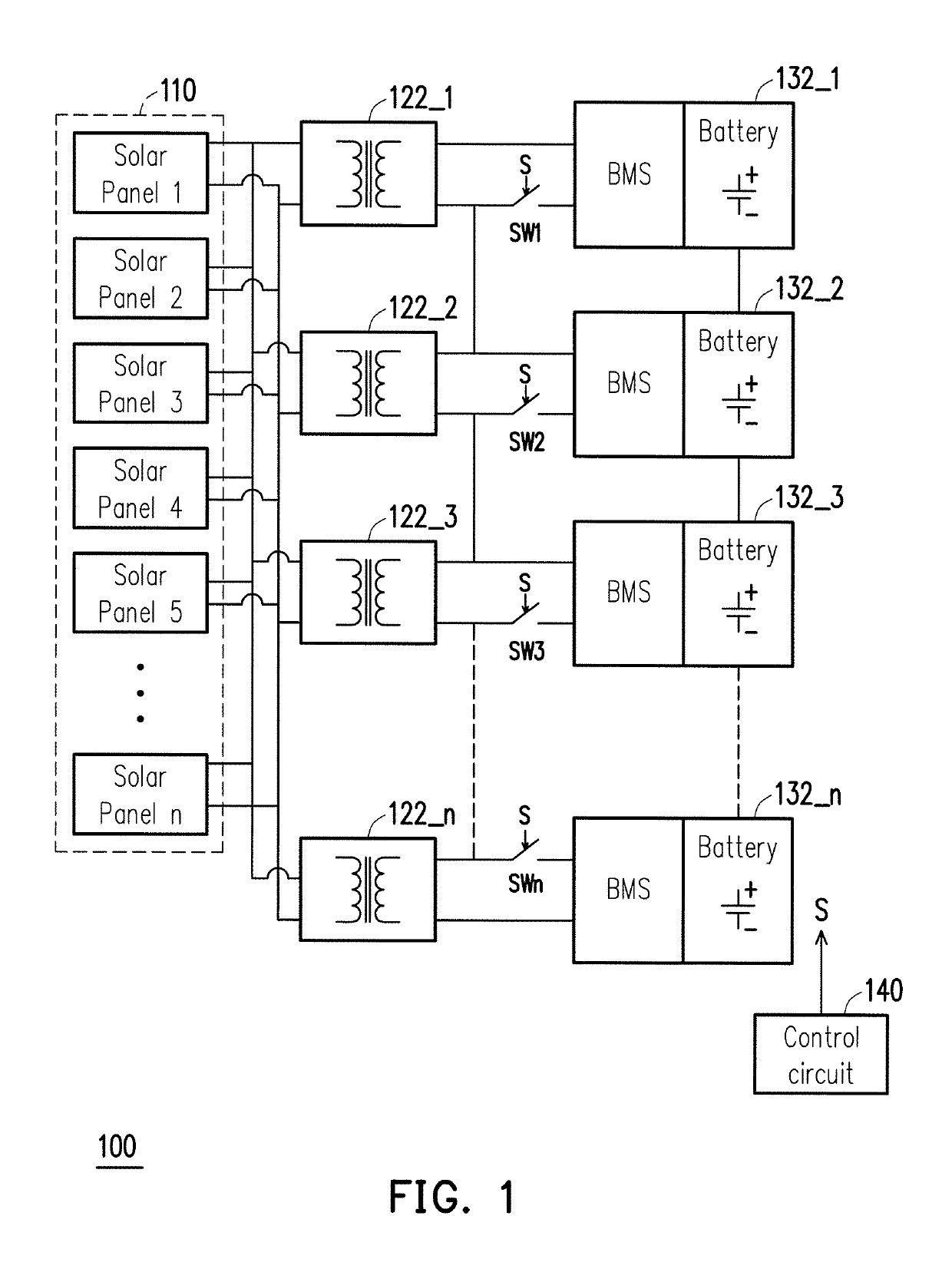
[0023]FIG. 1 illustrates a schematic diagram of the battery charging apparatus 100 which includes a charging power source 110, a plurality of charging circuits 122_1-122_n, a plurality of batteries 132_1-132_n, a plurality of switches SW1-SWn and a control circuit 140. The charging power source 110 is configured to supply charging power (energy) to the charging circuits 122_1-122_n so as to charge the batteries 132_1-132_n. In FIG. 1, the charging power source 110 is shown as solar panels 1˜n including a plurality of renewable energy sources (e.g., solar cells). However, the disclosure is not limited thereto, the charging power source 110 could be other sources such as wind turbine source, fuel cell...


PUM


Abstract

A battery charging apparatus includes a charging power source, a plurality of charging circuits, a plurality of batteries, a plurality of switching circuits and a control circuit. The control circuit is configured to determine the type of charging power source based on a current-voltage curve of the charging power source, and to control conduction states of the switching circuits to connect the charging circuits and the batteries in series in a series charging mode and to connect the charging circuits and the batteries in parallel in an equalizing charging mode. A battery charging method of the battery charging apparatus is also introduced.

Description

BACKGROUND OF THE INVENTION1. Field of the Invention[0001]This disclosure relates to rechargeable batteries, and particularly relates to a battery charging apparatus and a battery charging method that is capable of charging the rechargeable batteries with a series charging mode and an equalizing charging mode.2. Description of the Related Art[0002]Battery packs are used as an energy storage device in a variety of electronic devices, including portable computers, personal digital assistants (PDAs), cellular phones, and cameras, etc. In conventional arts of designing battery chargers, designer has to either make use of a dedicated high voltage (HV) for charring HV battery system or use a large number of low voltage (LV) chargers to charge every one of the battery modules within the battery system, respectively. On one hand, using the dedicated HV for charging HV battery system may suffer from imbalance which jeopardizes lifespan of the battery system in the long run. Further, using pl...

Claims


Application Information

Patent Timeline
IPC IPC(8): H01M10/44H02J7/00
CPCH01M10/441H02J7/0019H02J7/007H02J7/0018H02J7/35H02J7/00712Y02E60/10H02J7/00
Inventor HUANG, YU-HSIANGLO, YU-KANG
Owner LITE ON ELECTRONICS (GUANGZHOU) LTD
Why Eureka
Try Eureka