Structured Display System with System Defined Transitions

a display system and system defined technology, applied in the field of user interfaces, can solve the problems of affecting the user's experience, so as to reduce the disruption of the user and increase productivity

Active Publication Date: 2009-07-30
QUALCOMM INC
View PDF7 Cites 47 Cited by
  • Summary
  • Abstract
  • Description
  • Claims
  • Application Information

AI Technical Summary

Benefits of technology

[0013]For each application and each transition between successive views it is noted that the process maintains visual continuity with visual elements within successive views. Moreover, because system level parameters are used for managing user interface actions within an application, rather than having the application manage those aspects, t

Problems solved by technology

The frames, however, are static and lose relevance as views are changed.
This is often the problem with framed web pages.
Conventional user interfaces also are visually cumbersome.
For example, the user interface typically removes the prior view and redraws the new view, which can leave the user disoriented due to the break in visual continuity.
Even temporary disorientation by the user results in lost productivity and detachment from the interface interaction while the user reorients to the second view.
However, the applications created with these tools are “hard coded

Method used


Image

  • Structured Display System with System Defined Transitions
  • Structured Display System with System Defined Transitions
  • Structured Display System with System Defined Transitions

Examples


Embodiment Construction

[0022]The Figures (FIGS.) and the following description relate to preferred embodiments by way of illustration only. It should be noted that from the following discussion, alternative embodiments of the structures and methods disclosed herein will be readily recognized as viable alternatives that may be employed without departing from the principles described herein.

[0023]Reference will now be made in detail to several embodiments, examples of which are illustrated in the accompanying figures. It is noted that wherever practicable similar or like reference numbers may be used in the figures and may indicate similar or like functionality. The figures depict embodiments of the disclosed system (or method) for purposes of illustration only. One skilled in the art will readily recognize from the following description that alternative embodiments of the structures and methods illustrated herein may be employed without departing from the principles described herein.

Example Mobile Computin...


PUM


Abstract

A disclosed system (and method) is configured to receive an instruction to transition from a first view to a second view. The first view and the second view include two or more visual elements. The system receives data corresponding to visual elements in the first view and visual elements in the second view. The system groups the visual elements to include visual elements moved out between the first view and the second view, visual elements retained from the first view in the second view, and visual elements moved into the second view. The system retrieves a system defined transition style for rendering the visual elements between the first view and the second view. Using the groupings the system transitions the first view to render the second view through application of the transition style on the groups of visual elements.

Description

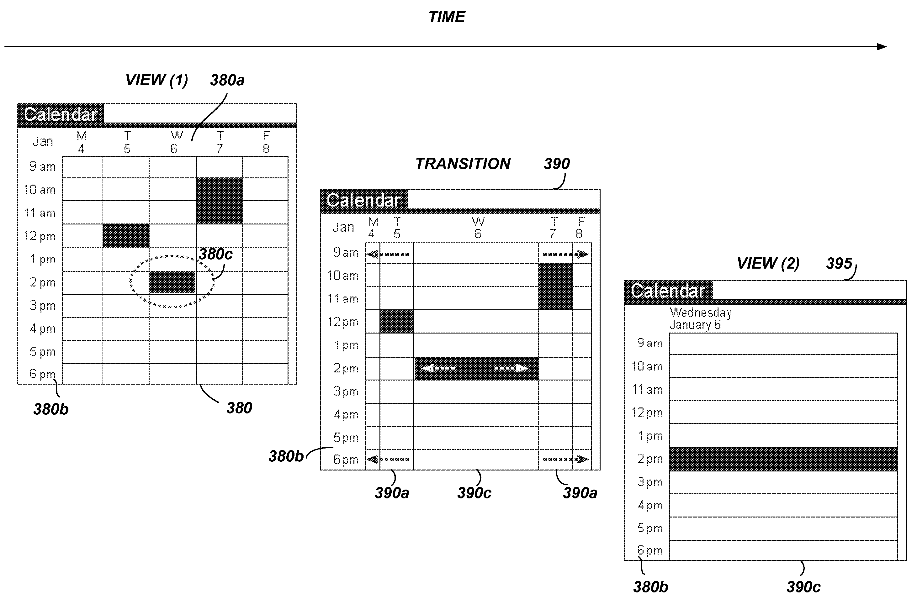
BACKGROUND[0001]1. Field of Art[0002]The disclosure generally relates to the field of user interfaces, and more specifically, to a user interface that maintains visual continuity and consistency of transitions between views during navigation.[0003]2. Description of the Related Art[0004]On conventional computing devices a user interface consists of a series of independent display renditions. For example, when in a calendar application, to switch from one view, e.g., a month view, to a second view, e.g., a week view, the calendar application had to replace the month view from the screen with the week view, even if the two views had one or more visual elements in common.[0005]In an attempt to maintain a semblance of continuity, some user interfaces frame a portion of the screen in order to keep context of subsequent views. The frames, however, are static and lose relevance as views are changed. This is often the problem with framed web pages. Moreover, the views that are changed within...

Claims


Application Information

Patent Timeline
IPC IPC(8): G09G5/00
CPCG06F9/4443G06F3/0482G06F9/451
Inventor MERCER, PAULTHOMAS, RALPH
Owner QUALCOMM INC
Why Eureka
Try Eureka