
Bag Computer with interior access coupling

a bag computer and interior access technology, applied in the field of computers, can solve the problems that the electrical access between computing equipment mounted to the inside and outside of the bag is not a new development, and achieve the effect of improving the utility of the invention

Inactive Publication Date: 2009-07-30
DALEY III CHARLES A
View PDF29 Cites 42 Cited by
  • Summary
  • Abstract
  • Description
  • Claims
  • Application Information

AI Technical Summary

Benefits of technology

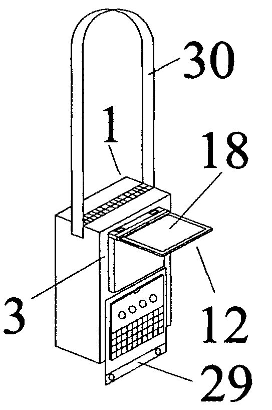
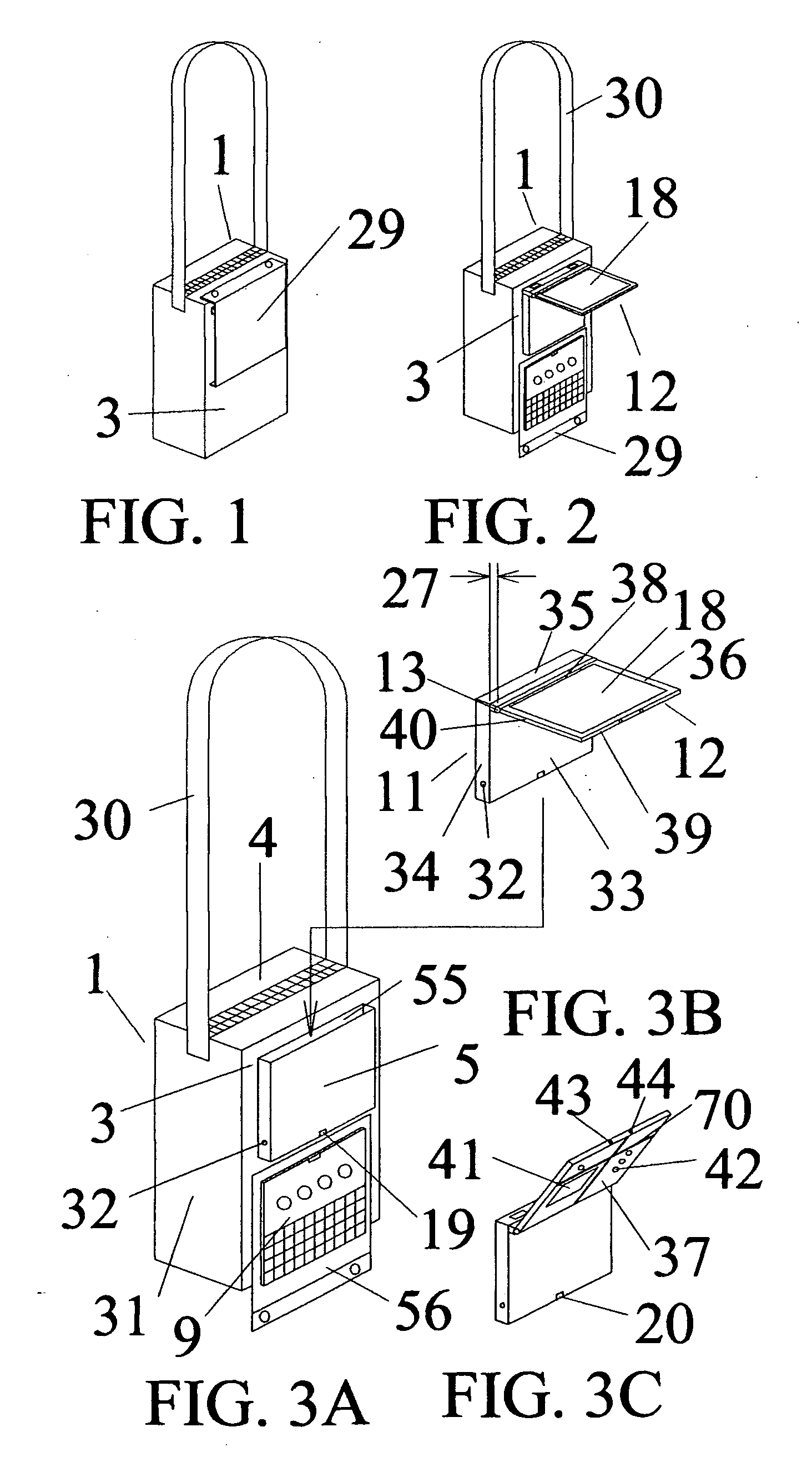
[0007]This application includes improvements on the bag computer, specifically communication between the outside mounted equipment and peripherals inside the bag. Electrical access between computing equipment mounted to the inside and outside of a bag is not a new development. However, in the context of the bag computer, inventive ways to communicate between the bag computer's outside mounted computing equipment and inside peripherals improve the utility of the invention.

Problems solved by technology

Electrical access between computing equipment mounted to the inside and outside of a bag is not a new development.

Method used


Image

  • Bag Computer with interior access coupling
  • Bag Computer with interior access coupling
  • Bag Computer with interior access coupling

Examples


second embodiment

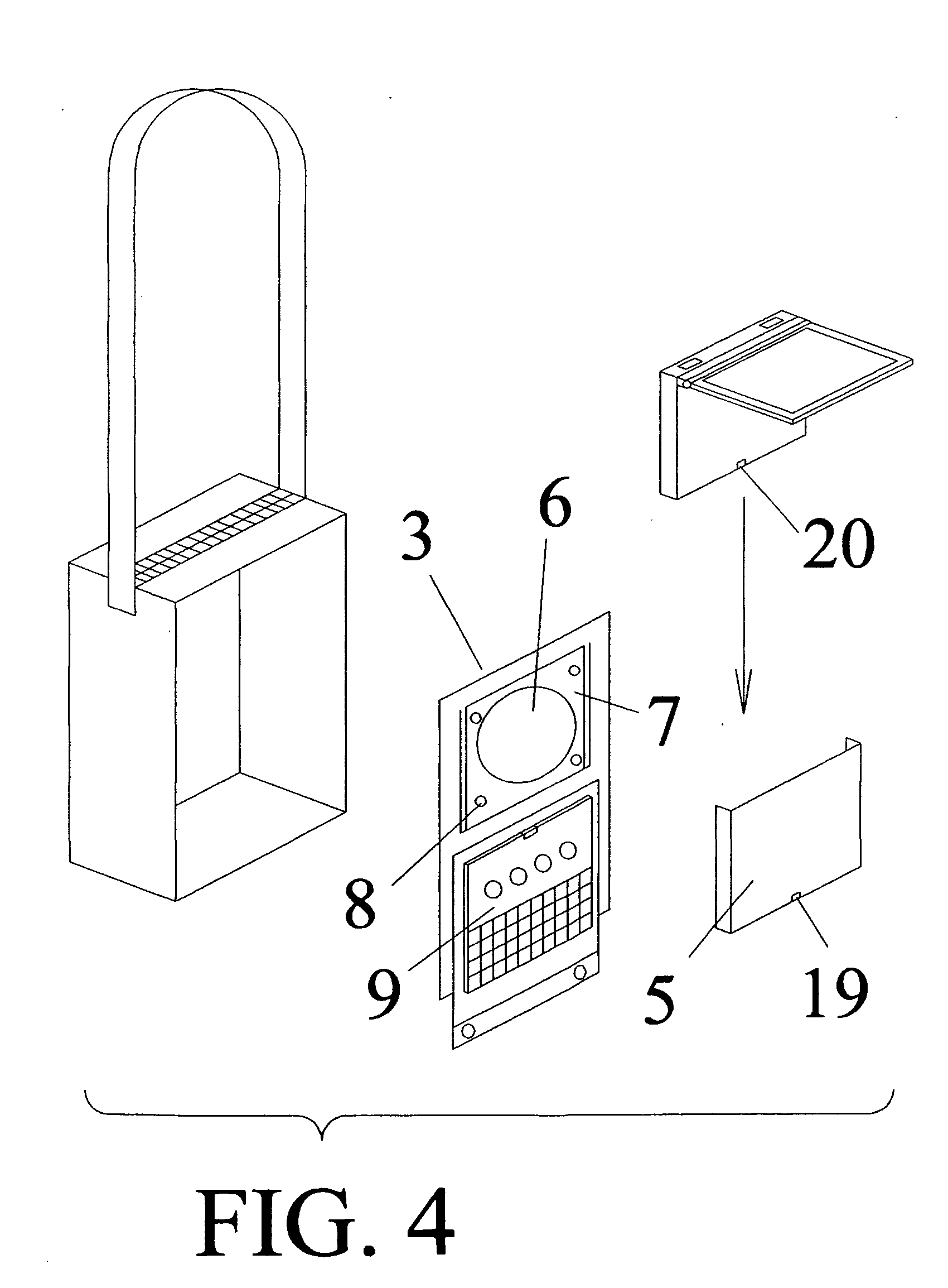
[0050]In a second embodiment, shown in exploded view FIG. 6, to provide access to controls, electrical plugs, peripherals and peripheral mounts on the back surface of the body panel, the interior access coupling is comprised of the two panel computer's body panel being divided into a back body panel part 21 and a front body panel part 22 which may be attached together with matching attachments through a pattern of holes 23 in the bag front wall 3. While clamping the two panel computer parts to the bag front wall, the matching attachments and bag holes also serve to secure the two panel computer to the bag and in computer holder, to align the parts, and to physically and electrically connect the front and back body parts.

[0051]The bag interior access coupling is comprised of a pattern of holes located on the bag front wall 3 adjacent to the computer holder 5 so that it may be engaged to the two panel computer while the body panel is in the computer holder. The holes may be trimmed, w...

third embodiment

[0058]A third embodiment, shown in exploded view FIG. 10, the interior access coupling provides access to two panel computer controls, electrical plugs and peripheral mounts by employing a bag front wall 3 electrical connection 52, which constitutes the bag part interior access coupling, adjacent to the back surface of the matching the body panel 11 when held in the computer holder 5. The bag interior access coupling is located on the bag front wall 3 adjacent to the computer holder 5 so that it is aligned with and may be engaged while the body panel is in the computer holder.

[0059]Shown in FIG. 11, a view of the inside surface of the bag front wall and back side of the two panel computer's body panel, the bag part interior access coupling, in this case a front wall electrical connection, is positioned on the exterior of front wall so it may be engaged to a matching two panel computer electrical connection 53, constituting the computer part interior access coupling, on the body pane...


PUM


Abstract

Disclosed is a bag computer comprised of a bag with holder and computer with display panel and body panels hinged together. The computer body installs into the holder so the display panel pivots near the top of the bag front with its display facing outward / upward so the bag wearer can store the display against the bag front or pivot it into his line of sight. To provide access between peripherals, memory or batteries inside the bag and the computer outside the bag, the bag's front wall may have; 1) an opening with coupling matching the computer back side; 2) a pattern of holes matching a computer with inside and outside body parts which join with attachments through the pattern of holes; 3) an electrical connection in the holder which connects the computer to a connection box inside bag.

Description

CROSS-REFERENCE TO RELATED APPLICATIONS[0001]This application is a Continuation-In-Part and claims the filing benefit under 35 U.S.C. §120 of pending U.S. application Ser. No. 11 / 796,920, filed May 1, 2007 and is incorporated herein by reference.[0002]This application claims the filing benefit under 35 U.S.C. §119(e) of U.S. Provisional Application No. 61 / 124,239, filed on Apr. 18, 2008, the entire teachings of which are incorporated herein by reference.[0003]This application claims the filing benefit under 35 U.S.C. §119(e) of U.S. Provisional Application No. 61 / 125,717, filed on Apr. 29, 2008, the entire teachings of which are incorporated herein by reference.[0004]This application claims the filing benefit under 35 U.S.C. § 119(e) of U.S. Provisional Application No. 61 / 123,308, filed on Apr. 8, 2008, the entire teachings of which are incorporated herein by reference.TECHNICAL FIELD[0005]The present invention relates to a computer designed for mobile use.BACKGROUND OF THE INVENTIO...

Claims


Application Information

Patent Timeline
Patent Type & Authority Applications(United States)
IPC IPC(8): G06F1/16
CPCG06F1/1628
Inventor DALEY, III, CHARLES A.
Owner DALEY III CHARLES A
Learn More