Fast reactor having reactivity control reflector

a fast reactor and reflector technology, applied in the direction of nuclear reactors, nuclear elements, greenhouse gas reduction, etc., can solve the problems of b>5/b> being damaged, and achieve the effect of high reliability, high efficiency, and excellent sound structure and productivity

Inactive Publication Date: 2009-07-30
KK TOSHIBA
View PDF13 Cites 16 Cited by
  • Summary
  • Abstract
  • Description
  • Claims
  • Application Information

AI Technical Summary

Benefits of technology

[0019]In the present invention having the arrangement described above, the neutron reflector excellent in soundness of structure and productivity can be realized, and a highly reliable fast reactor having a reactivity control reflector can be provided.
[0020]Further, the fast reactor having the reactivity control reflector according to the present invention can realize a neutron reflector which is unlike to be deformed by thermal expansion and thermal stress and can provide a reflector which is excellent not only in soundness of structure and maintenance property but also in productivity, less affects core reactivity even if a cavity portion is broken, and can keep the function of the cavity portion.
[0021]Further, according to the fast reactor having the reactivity control reflector of the present invention, there can be provided a highly reliable fast reactor with a long life which can increase the reactivity control capability of a reflector. In addition, the soundness of structure can be improved by preventing the breakage of a neutron absorbing portion of a reflector, and an increase of the core reactivity can be also prevented.

Problems solved by technology

In addition to the above, it is also considered that the reflector 5 may be damaged by thermal stress and creep caused by the temperature difference in the reflector 5.
Further, when a box-shaped cavity portion is employed as the cavity portion 5b of the reactor 5, a problem arises in how the cavity portion 5b of the reflector 5 is to be arranged to prevent damage and breakage of the box member to prevent buckling due to thermal expansion difference caused by the temperature difference between the core barrel 4 and the partition wall 9.

Method used


Image

  • Fast reactor having reactivity control reflector
  • Fast reactor having reactivity control reflector
  • Fast reactor having reactivity control reflector

Examples


first embodiment

Modification of First Embodiment

[0080]FIG. 10 shows a modification of the first embodiment of the fast reactor having the reactivity control reflector.

[0081]Since the overall arrangement of a fast reactor having a reactivity control reflector shown in the modification is not different from that shown in FIGS. 1 to 8, the same arrangements are denoted by the same reference numerals and the explanation thereof is omitted.

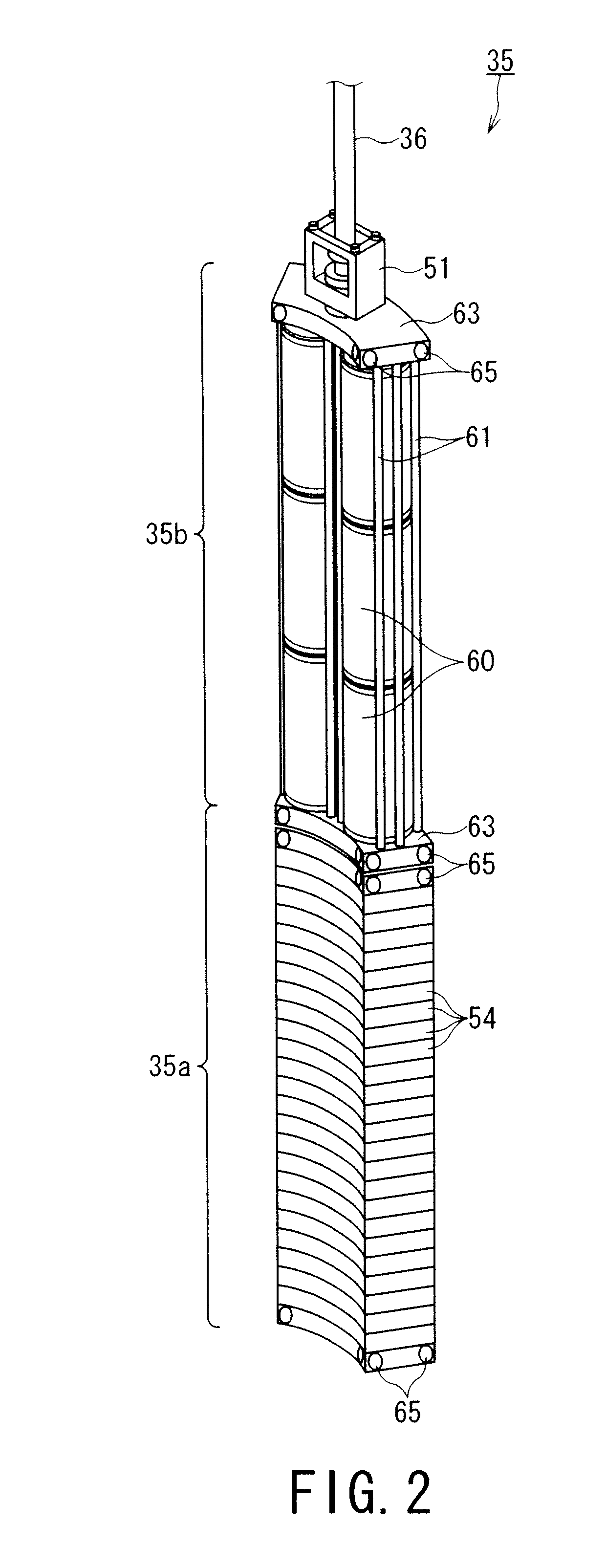
[0082]In FIG. 10, a cavity portion 35b of a reflector 35 is composed of a plurality of cylindrical hermetically-sealed vessels 60 in total of, for example, six pieces, in which two pieces are arranged horizontally in rows and three pieces are stacked vertically in column, and the hermetically-sealed vessels 60 of the cavity portion 35b are arranged as an integral structure by being welded to partition wall 70. The respective hermetically-sealed vessels 60 of the cavity portion 35b may be arranged as the integral structure by welding each column thereof to the partitio...

second embodiment

Modification of Second Embodiment

[0091]FIGS. 12A to 12C represent a modification of the second embodiment of the fast reactor having the reactivity control reflector.

[0092]In FIGS. 12A to 12C, the overall arrangement of a fast reactor having a reactivity control reflector is not different from that of the first embodiment shown in FIGS. 1 to 8 except for a cavity portion 35b of a reflector 35 disposed to the fast reactor, in which arrangement of the hermetically-sealed vessels is changed according to design condition. Accordingly, the same arrangements are denoted by the same reference numeral and the explanation thereof is omitted.

[0093]In FIG. 12A, a plurality of, for example, nine hermetically-sealed vessels 76, which have a medium diameter, smaller than the diameter of the hermetically-sealed vessels 75 disposed in FIG. 11, are disposed in the cavity portion 35b of the reflector 35 in a column state. The respective hermetically-sealed vessels 76 are selected so as to have the sa...

third embodiment

[0099]Next, a third embodiment of the fast reactor having the reactivity control reflector according to the present invention will be explained with reference to FIGS. 13 to 15B.

[0100]Since the overall arrangement of a fast reactor 20A of the third embodiment is not different from that of the fast reactor 20 of the first embodiment except the structure of a reflector, the same arrangements are denoted by the same reference numerals and the explanation thereof is simplified.

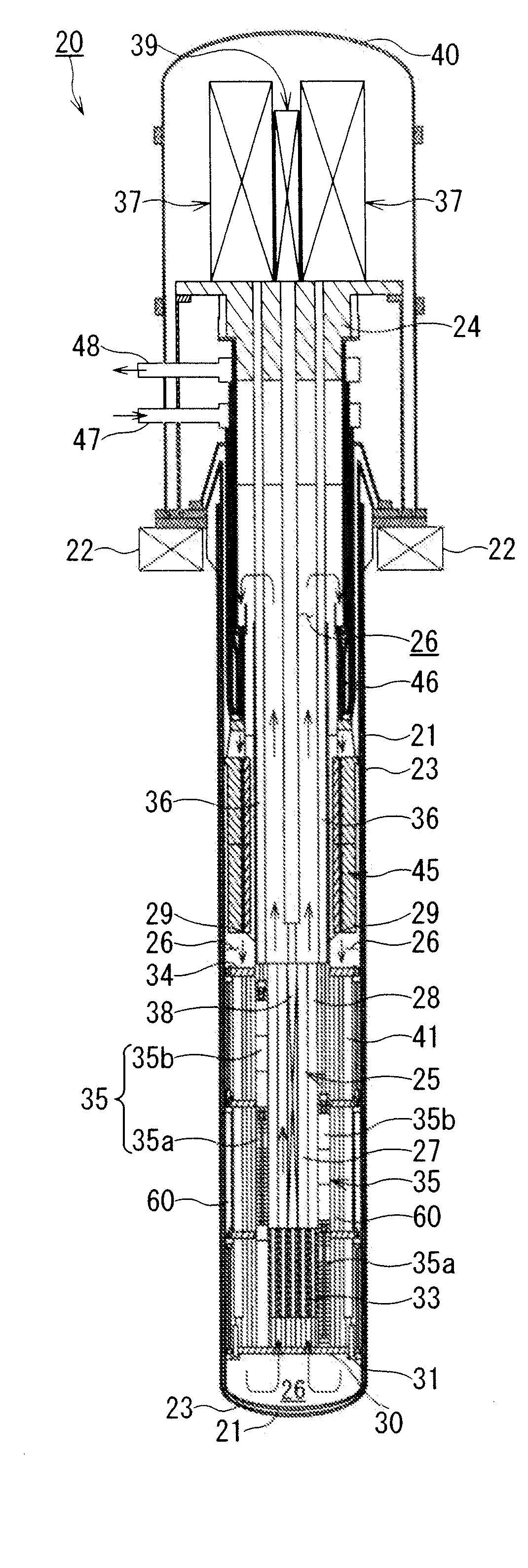
[0101]As shown in FIG. 13, the fast reactor 20A having the reactivity control reflector has a reactor vessel 21 in which a primary coolant 26 is accommodated, a reactor core 25 installed in the reactor vessel 21 and dipped into the primary coolant 26, and a reflector 85 which is vertically movably installed outside of the periphery of the reactor core 25 so as to control the reactivity of the reactor core 25 by adjusting the leakage of the neutrons generated from the reactor core 25 by moving in the vertical direc...


PUM


Abstract

A fast reactor having a reactivity control reflector has a reactor vessel in which a coolant is accommodated, a reactor core which is installed in the reactor vessel and dipped with the coolant, and a reflector installed outside of the reactor core so as to be movable in a vertical direction for controlling the reactivity of the reactor core. The reflector of the fast reactor has a lower neutron reflecting portion having a neutron reflection capability higher than that of the coolant and an upper cavity portion located above the neutron reflecting portion and having a neutron reflection capability lower than that of the coolant. The cavity portion is composed of a plurality of cylindrical hermetically-sealed vessels.

Description

BACKGROUND OF THE INVENTION[0001]1. Field of the Invention[0002]The present invention relates to a fast reactor having a reactivity control reflector for controlling the reactivity of a reactor core by moving reflectors upward and downward, and more particularly to a fast reactor having a reactivity control reflector which is excellent in soundness of structure and has high reliability.[0003]2. Related Art[0004]Patent Document 1 (Japanese Unexamined Patent Application Publication No. 6-174882) discloses an example of conventional fast reactors, which is shown in FIG. 21. The conventional fast reactor 1 has a reactor core 3 which is accommodated in a reactor vessel 2 and in which a nuclear fuel assembly is loaded. The reactor core 3 is formed in an approximately columnar shape, and the outer periphery thereof is surrounded by a core barrel 4 for protecting the reactor core 3. A reflector 5 is installed outside of the core barrel 4. The reflector 5 is coupled with a reflector drive ap...

Claims


Application Information

Patent Timeline
Patent Type & Authority Applications(United States)
IPC IPC(8): G21C11/06
CPCG21C1/02G21C7/10Y02E30/39G21C11/06Y02E30/34G21C7/28Y02E30/30
Inventor SAKAI, TOSHIROINATOMI, TAKANARINAKAMURA, HIROSHIFUKAMICHI, KENJIROSUZUKI, TOSHIYUKIHASEGAWA, KATSUSHITSUBOI, YASUSHIKURAMOCHI, MAKOTO
Owner KK TOSHIBA
Why Eureka
Try Eureka