
Belt drive control unit, belt drive control method, belt drive control program, and image forming apparatus using same

a control unit and control method technology, applied in the direction of electrographic process apparatus, instruments, optics, etc., can solve the problems of color-to-color displacement, image failure, control may not be effective for keeping the transport speed of the endless belt constant,

Inactive Publication Date: 2009-07-30
RICOH KK
View PDF5 Cites 25 Cited by
  • Summary
  • Abstract
  • Description
  • Claims
  • Application Information

AI Technical Summary

Benefits of technology

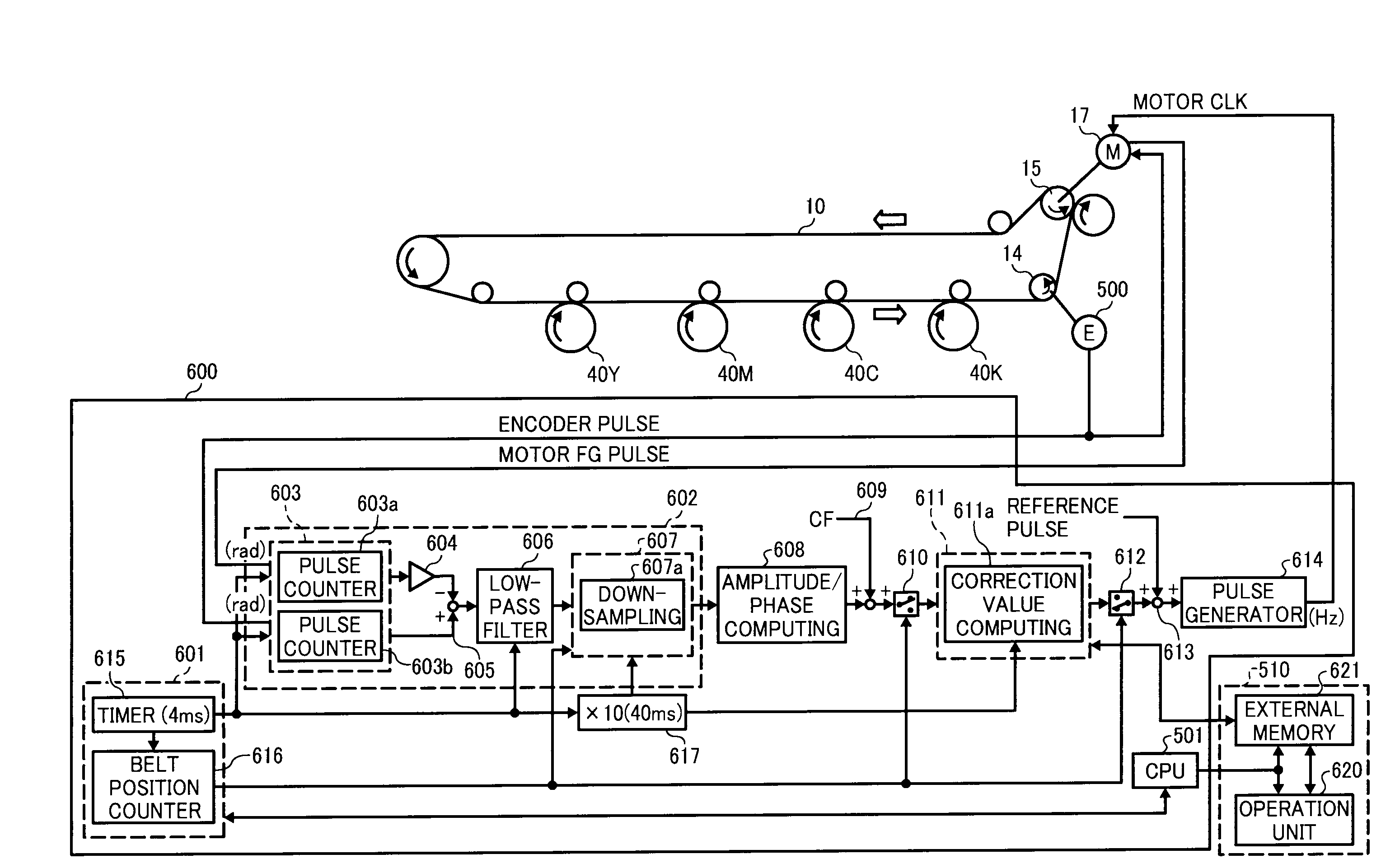
[0028]In an aspect of the present disclosure, a belt drive control unit controls a rotation movement of a belt extendedly supported by a first rotatable device and a second rotatable device. The first rotatable device is used as a drive-type rotatable device to support and rotate the belt. The drive-type rotatable device is driven by a driver. The second rotatable device is used as a driven-type rotatable device. The second rotatable device is rotatable when the belt rotates. A rotation of the drive-type rotatable device is detected by a first detector as a first detection result. A rotation of the driven-type rotatable device is detected by a second detector as a second detection result. A rotation of the drive-type rotatable device is controlled in connection with thickness fluctuation in the belt at the driven-type rotatable device using the first detection result and the second detection result. The belt drive control unit includes a sampling data acquisition unit, a correction value generation unit, a correction value storage device, and a correction value reading control unit. The sampling data acquisition unit obtains sampling data by sampling a difference value between the first detection result and the second detection result. The correction value generation unit generates correction value data for each number of rotations of the belt based on the sampling data, the correction value data is used to correct a rotation of the drive-type rotatable device. The correction value storage device stores the correction value data. The correction value reading control unit reads the correction value data stored in the correction value storage device at a timing determined by number of rotations of the belt for controlling a rotation of the drive-type rotatable device.
[0029]In another aspect of the present disclosure, a belt drive control method is used to control a rotation movement of a belt extendedly supported by a first rotatable device and a second rotatable device. The first rotatable device is used as a drive-type rotatable device to support and rotate the belt. The drive-type rotatable device is driven by a driver. The second rotatable device is used as a driven-type rotatable device. The second rotatable device rotatable when the belt rotates. A rotation of the drive-type rotatable device is detected by a first detector as a first detection result. A rotation of the driven-type rotatable device is detected by a second detector as a second detection result. A rotation of the drive-type rotatable device is controlled in connection with thickness fluctuation in the belt at the driven-type rotatable device using the first detection result and the second detection result. The method comprising the steps of acquiring sampling data, generating correction value data, storing correction value data, and reading correction value data. In the acquiring sampling data, a difference value between the first detection result and the second detection result are sampled to obtain sampling data. In the generating correction value data, correction value data for correcting a rotation of the drive-type rotatable device is generated according to number of rotations of the belt based on the sampling data. In storing correction value data, the correction value data generated by the generation step is stored in a correction value storage device according to number of rotations of the belt. In the reading correction value data, the correction value data stored in the correction value storage device is read according to number of rotations of the belt.
[0030]In another aspect of the present disclosure, a computer readable medium stores a program of belt drive control, comprising computer readable instructions, that when executed by a computer, that instructs a belt drive control unit to carry out a method of controlling a rotation movement of a belt extendedly supported by a first rotatable device and a second rotatable device. The first rotatable device is used as a drive-type rotatable device to support and rotate the belt. The drive-type rotatable device is driven by a driver. The second rotatable device is used as a driven-type rotatable device. The second rotatable device rotatable when the belt rotates. A rotation of the drive-type rotatable device is detected by a first detector as a first detection result. A rotation of the driven-type rotatable device is detected by a second detector as a second detection result. A rotation of the drive-type rotatable device is controlled in connection with thickness fluctuation in the belt at the driven-type rotatable device using the first detection result and the second detection result. The method comprising the steps of acquiring sampling data, generating correction value data, storing correction value data, and reading correction value data. In the acquiring sampling data, a difference value between the first detection result and the second detection result are sampled to obtain sampling data. In the generating correction value data, correction value data for correcting a rotation of the drive-type rotatable device is generated according to number of rotations of the belt based on the sampling data. In storing correction value data, the correction value data generated by the generation step is stored in a correction value storage device according to number of rotations of the belt. In the reading correction value data, the correction value data stored in the correction value storage device is read according to number of rotations of the belt.

Problems solved by technology

In such image forming apparatuses, color-to-color displacement may occur if a moving (or traveling) velocity of the endless belt cannot be kept constant.
Color-to-color displacement may be observed as incorrect superimposing of different color images, which causes image failure.
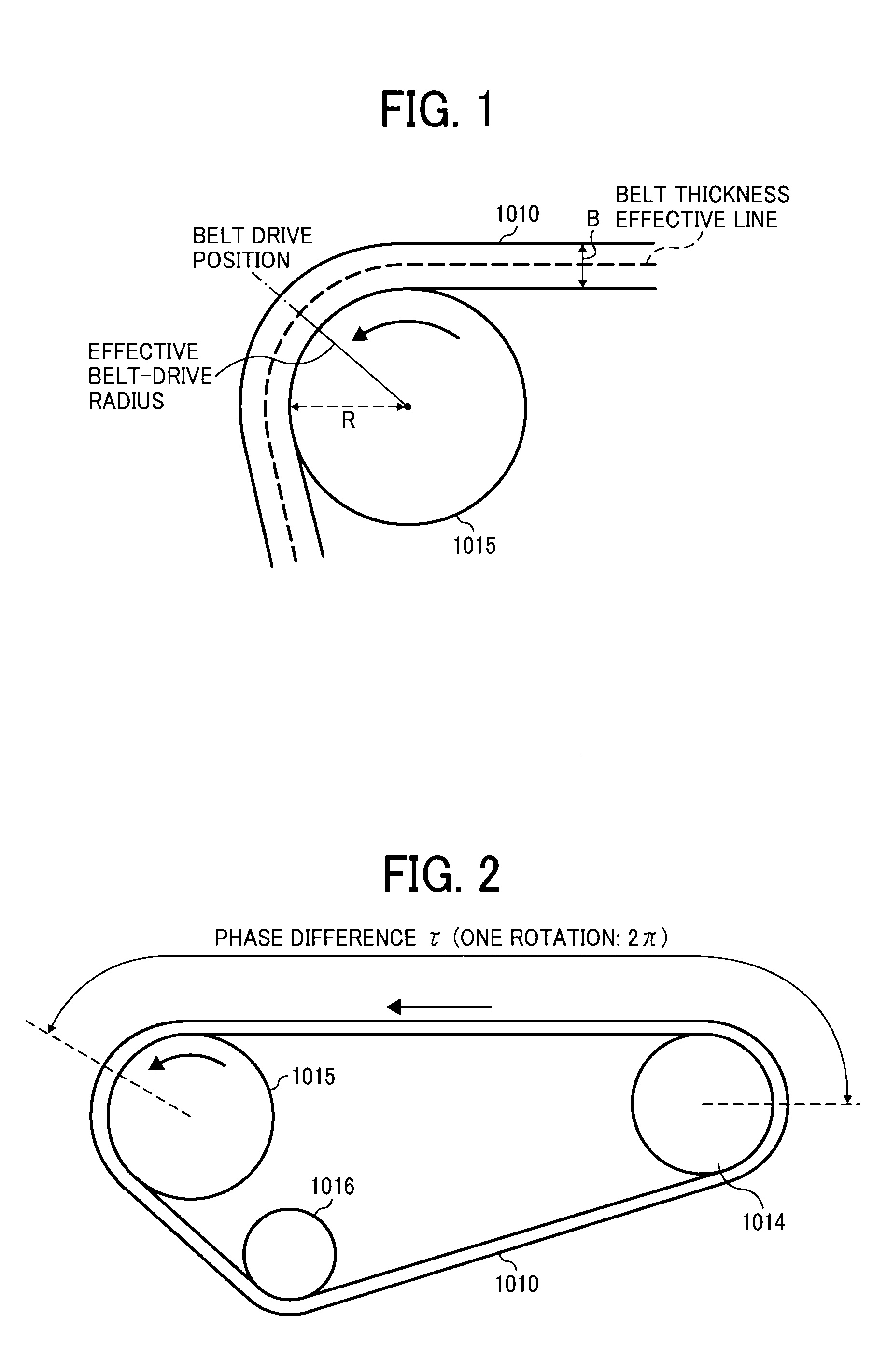
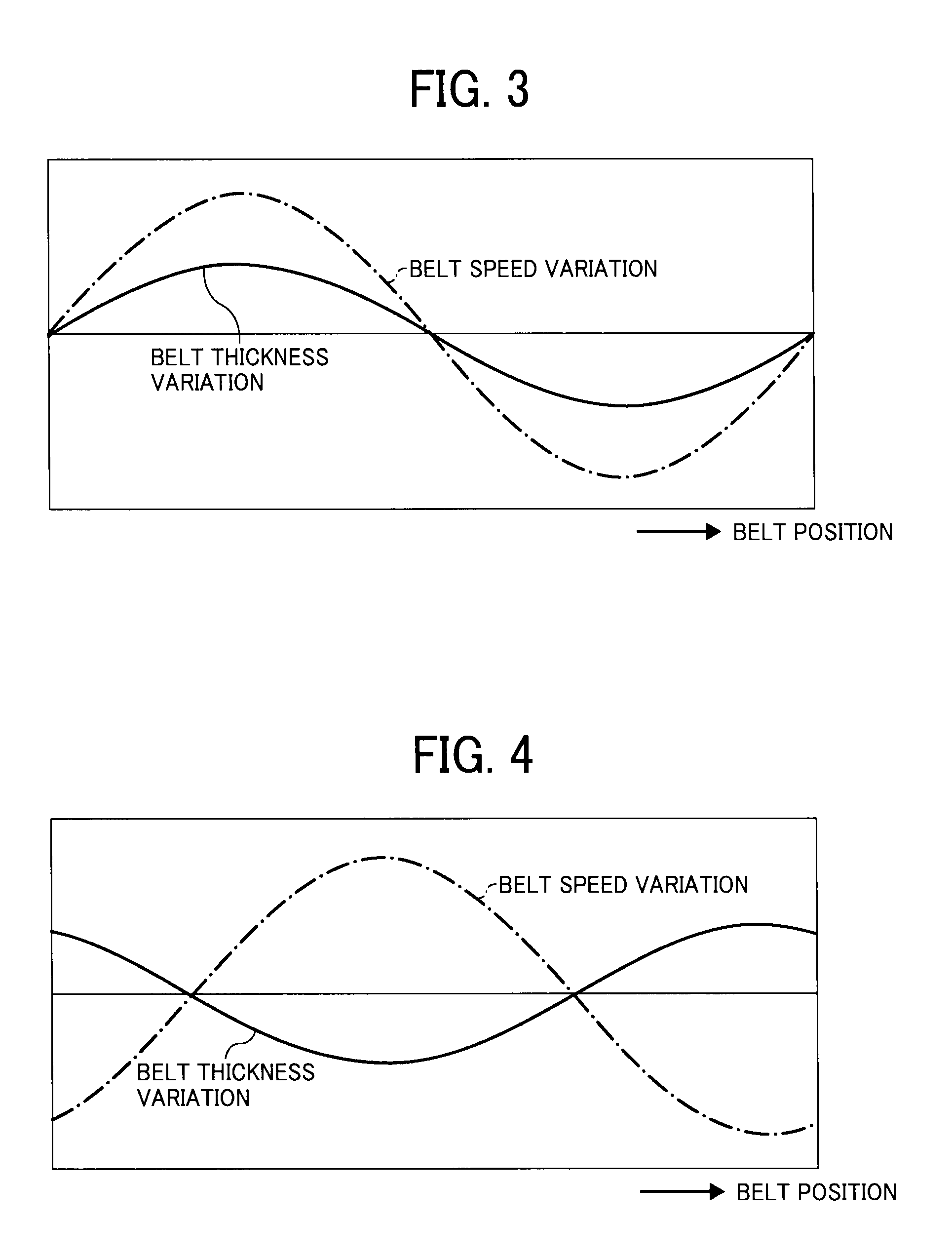
However, such control may not be effective for keeping the transport speed of the endless belt constant because fluctuation or variation in a thickness of the endless belt, which may be small in absolute terms, nevertheless may be sufficiently large to cause the transport speed of the endless belt to fluctuate.
If a transport speed of transfer sheet or intermediate transfer member fluctuates, image quality may be degraded, and images cannot be produced reliably on the transfer sheet because an image-receiving position on the target transfer sheet or the intermediate transfer member may deviate due to such fluctuation.
Further, such fluctuation in transport speed may cause undesirable effects when images are reproduced on multiple transfer sheets.
Accordingly, a conventional feedback control using the driven roller may not be effective in view of a thickness fluctuation in the belt because the speed detection results may falsely indicate a speed fluctuation in the endless belt.
If a control cycle is set short, a large capacity memory may be needed, whereas if the control cycle is set long, feedback control may not be conducted effectively.
Accordingly, in addition to a memory used as a working area, another memory may also be required, which increases a total cost of the apparatus.
However, the thickness fluctuation in the transfer belt needs to be measured at a higher precision of several micrometers (μm) or so, and an input error may occur when inputting data because the amount of measured data may become great.

Method used


Image

  • Belt drive control unit, belt drive control method, belt drive control program, and image forming apparatus using same
  • Belt drive control unit, belt drive control method, belt drive control program, and image forming apparatus using same
  • Belt drive control unit, belt drive control method, belt drive control program, and image forming apparatus using same

Examples


Embodiment Construction

[0053]A description is now given of example embodiments of the present invention. It should be noted that although such terms as first, second, etc. may be used herein to describe various elements, components, regions, layers and / or sections, it should be understood that such elements, components, regions, layers and / or sections are not limited thereby because such terms are relative, that is, used only to distinguish one element, component, region, layer or section from another region, layer or section. Thus, for example, a first element, component, region, layer or section discussed below could be termed a second element, component, region, layer or section without departing from the teachings of the present invention.

[0054]In addition, it should be noted that the terminology used herein is for the purpose of describing particular embodiments only and is not intended to be limiting of the present invention.

[0055]Thus, for example, as used herein, the singular forms “a”, “an” and “...


PUM


Abstract

A belt drive control unit controls a rotation of belt supported by first and second rollers. Each of rotations of the first and second rollers are detected as first and second results. A rotation of the first roller is controlled in connection with thickness fluctuation in the belt using the first and second results. The belt drive control unit includes a sampling data acquisition unit, a correction value generator, a correction value storage, and a correction value reading controller. The sampling data acquisition unit obtains sampling data by sampling a difference value between the first and second results. The correction value generator generates correction value data for the belt based on the sampling data. The correction value storage stores the correction value data. The correction value reading controller reads the correction value data based on a rotation number of the belt to control a rotation of the first roller.

Description

CROSS-REFERENCE TO RELATED APPLICATIONS[0001]This application claims priority under 35 U.S.C. 119(a) to Japanese Patent Application Nos. 2008-019468, filed on Jan. 30, 2008, 2008-139945, filed on May 28, 2008, and 2009-015565, filed on Jan. 27, 2009 in the Japan Patent Office, the entire contents of each of which are hereby incorporated by reference herein.BACKGROUND OF THE INVENTION[0002]1. Field of the Invention[0003]The present disclosure generally relates to an image forming apparatus including a belt extended by a plurality of rotatable supporters and a belt drive control unit for controlling a driving of the belt, and a program for a belt drive control unit.[0004]2. Description of the Background Art[0005]Typically, image forming apparatuses employ either a direct transfer method or an indirect transfer method for forming a color image on a recording medium. In the direct transfer method, toner images formed on a plurality of photoconductors are directly transferred to a transf...

Claims


Application Information

Patent Timeline
Patent Type & Authority Applications(United States)
IPC IPC(8): G03G15/01
CPCG03G15/0131G03G2215/0158G03G2215/00139
Inventor OHKUBO, HIROKIMATSUDA, HIROMICHIANDOH, TOSHIYUKIMATSUDA, YUJIUEDA, YUICHIROKOBAYASHI, KAZUHIKOUEHARA, TAKUYAMURATA, TAKUYA
Owner RICOH KK
Learn More