Construction system and applications thereof

a construction system and construction technology, applied in the field of construction systems, can solve the problems of limiting the application scope of coupling members, affecting the character of couplings, and affecting the effect of couplings, etc., and achieve the effect of reducing friction

Inactive Publication Date: 2009-07-30
STEVKOVSKI SASO
View PDF14 Cites 5 Cited by
  • Summary
  • Abstract
  • Description
  • Claims
  • Application Information

AI Technical Summary

Benefits of technology

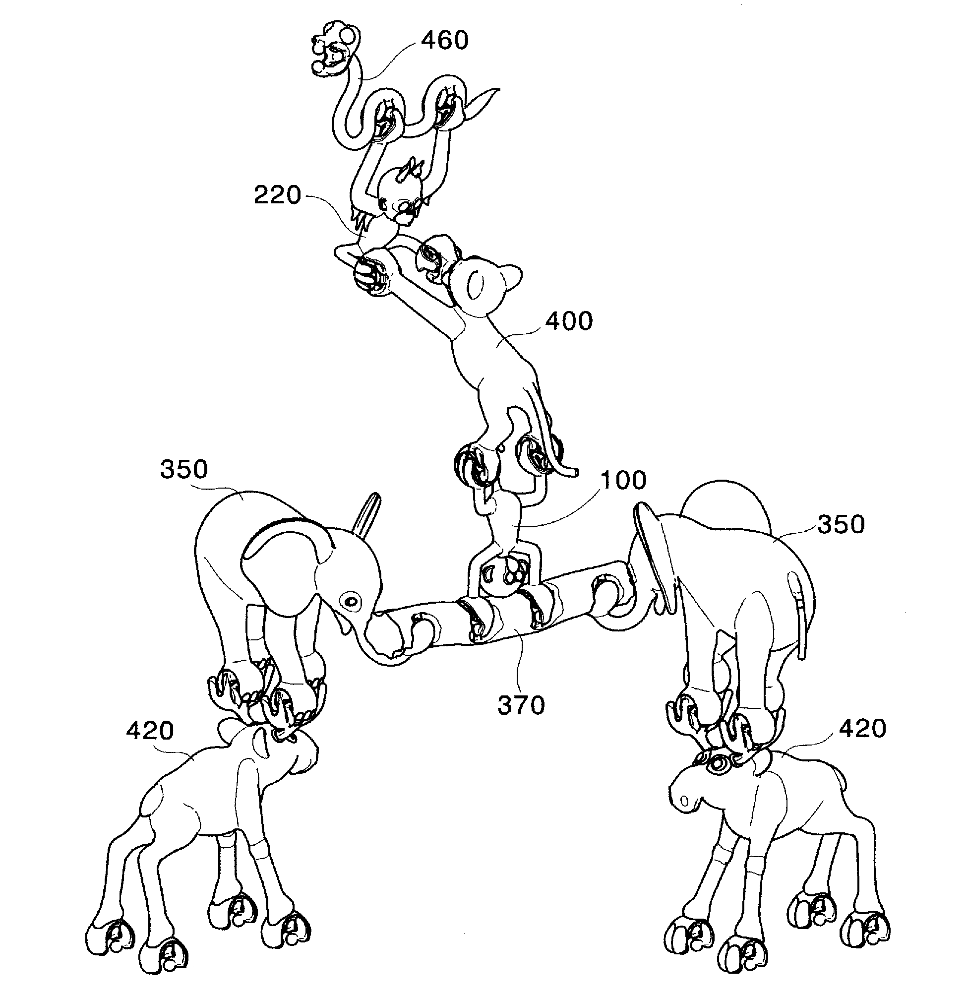
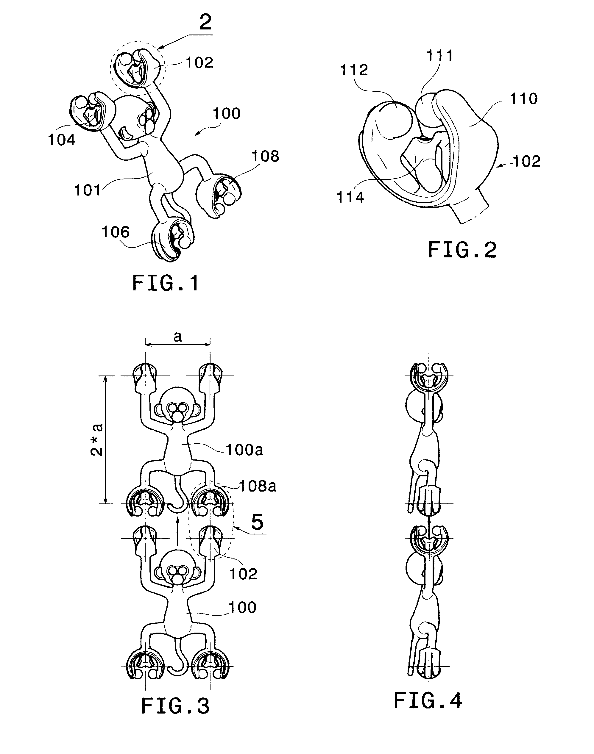
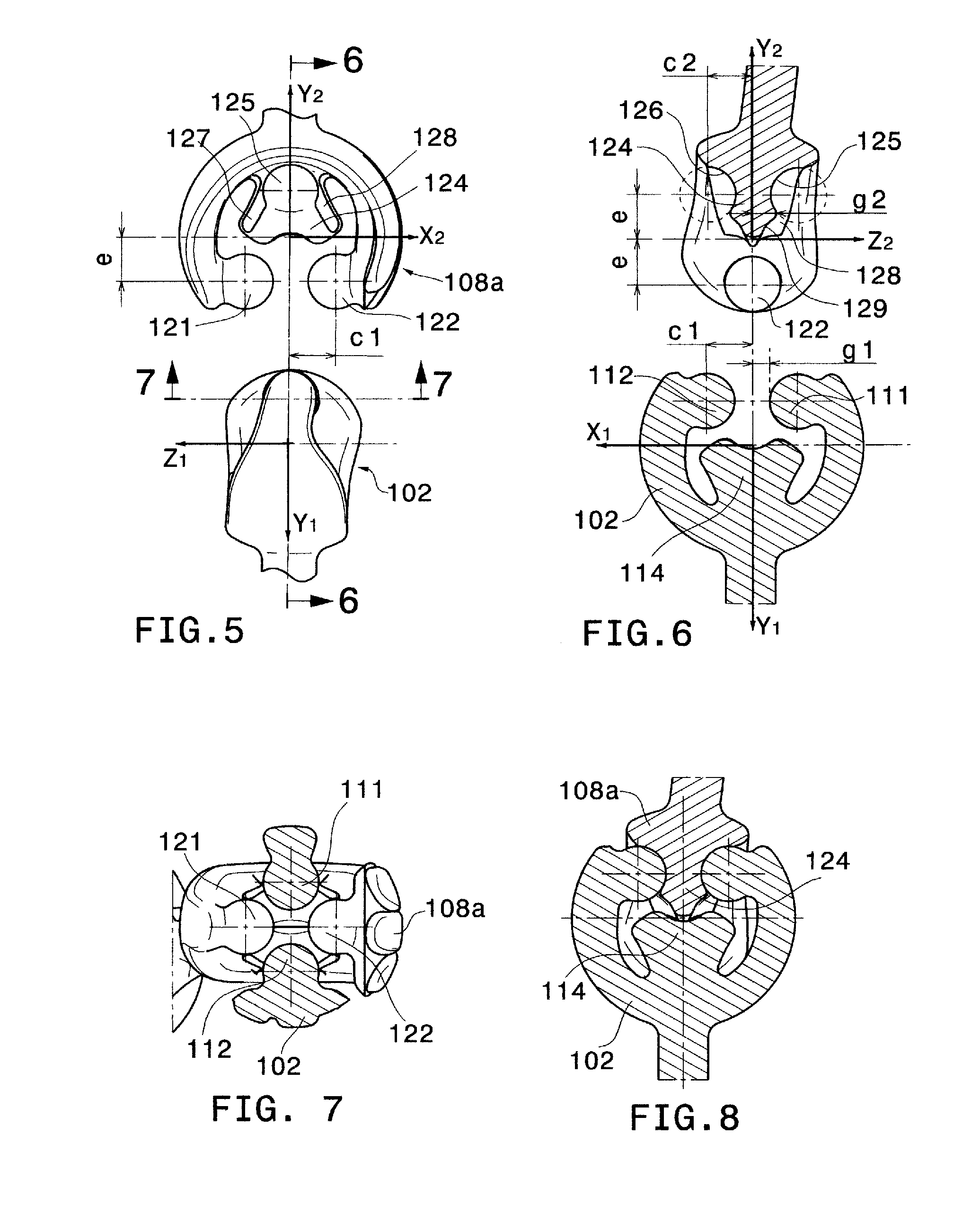
[0016]2) An exterior portion having an open loop shape with two wings, such as C-shape or U-shape. The function of this portion is to integrate the interior locking means into a functionally and visually compact unit, and to provide a resilient force when the wings are deflected or retracted during the engagement or disengagement of the couplings members.
[0017]This separation of functions allows for unlimited possibilities for geometric and stylistic execution of the exterior portion, as long as the required resilient force is provided. The interior locking portion, on the other hand, remains generally hidden once a connection has taken place.

Problems solved by technology

The function of the above, as well as other systems known in prior art, is inevitably linked to the geometric shape of the connecting resilient jaws or sockets, which limits their application scope.
For instance, stylistic variations or more radical geometric adjustments of the coupling members are generally not possible because their functionality could be adversely affected.
Furthermore, connections of such character tend to decouple easily even if a force is applied in directions other than the desired decoupling direction, which comes from the fact that the resisting resilient force is distributed all along the interface contours and in various directions depending on the curvature of the coupling member.
Such behaviour is mostly apparent in cases where a force that causes a moment about the centre of the connection is applied to one of the connected elements, in which case the coupled contours slip away from each other resulting ultimately in decoupling.

Method used


Image

  • Construction system and applications thereof
  • Construction system and applications thereof
  • Construction system and applications thereof

Examples


Embodiment Construction

[0130]Another similar construction element 140 is shown in FIG. 10, wherein the four coupling members are positioned at 2 times the unit distance “a” in horizontal and vertical direction, and the coupling directions are oriented at 45-degree angles with respect to the horizontal and vertical direction. This is illustrated with the axes y11 and y12 in FIG. 10, the opposite coupling members being symmetrical with respect to the vertical centerline.

[0131]FIGS. 11 and 12 depict another construction element 150. As seen in the side view (FIG. 12), the centers of the four coupling members are positioned on a circle with radius R1 and compose an angle of 60 degrees, the coupling directions y15 and y16 being tangent to the same circle.

[0132]FIG. 13 illustrates a construction element 160 where the centers of the upper two coupling members lie on a first circle with radius R2 and compose an angle of 60 degrees, while the centers of the lower two coupling members lie on a second circle with ra...


PUM


Abstract

A construction system includes a plurality of construction elements having body member and a plurality of coupling members, each of said coupling members having an exterior portion and an interior locking device of hermaphroditic type. The interior locking device includes protrusions and a receiving block. A first coupling member belonging to one construction element can interlock with a second coupling member belonging to another element, so that the protrusions of the first coupling member resiliently deflect away from each other and subsequently retract, and settle, into provided recesses in the receiving block of the second element. Concurrently, the protrusions of the second coupling member settle into corresponding recesses in the receiving block of the first coupling member. Applications of the construction system in toy construction sets, construction puzzles and board games are provided.

Description

BACKGROUND OF THE INVENTION[0001]1. Technical Field of the Invention[0002]The present invention relates, generally, to a construction system having a plurality of construction elements, and specifically to construction elements having identically shaped interlocking portions.[0003]The present invention, more particularly, relates to applications of the construction system in toy construction sets, two-dimensional or three-dimensional construction puzzles and board games.[0004]2. Description of the Prior Art[0005]At present, there exist numerous construction systems that include male and female interlocking members. Also known in the prior art are construction systems including identically shaped interlocking portions.[0006]One such construction system is disclosed in U.S. Pat. No. 4,548,590, wherein resiliently openable jaws provide means for connection. U.S. Pat. No. 5,897,417 discloses a socket-to-socket construction system where the interlocking sockets form a sphere. The interlo...

Claims


Application Information

Patent Timeline
Patent Type & Authority Applications(United States)
IPC IPC(8): A63H33/06
CPCA63F2003/0022A63H33/062A63F2003/00735
Inventor STEVKOVSKI, SASO
Owner STEVKOVSKI SASO
Why Eureka
Try Eureka