Valve lift device for a combustion engine

a technology of valve lift and combustion engine, which is applied in the direction of valve arrangements, machines/engines, mechanical equipment, etc., can solve the problems of low exhaust temperature, loss, and inability to close the inlet valve late in all operating conditions, and achieve good precision and friction between the guide surface and the contact devi

Inactive Publication Date: 2014-07-08
SCANIA CV AB
View PDF13 Cites 2 Cited by
  • Summary
  • Abstract
  • Description
  • Claims
  • Application Information

AI Technical Summary

Benefits of technology

[0008]The object of the present invention is to propose a valve lift device for a combustion engine which allows variable opening time and / or variable closing time for a valve which may be an inlet valve or an exhaust valve.
[0011]According to another preferred embodiment of the present invention, said first and second units are connected to the motion-transmitting mechanism in such a way that the unit which at the time is subject to the higher lift of its guide surface transmits that lift to the valve. When the respective contact device of the units are in corresponding contact positions on the identically shaped guide surfaces, the units undergo a simultaneous lift. Moving the contact device of the first unit to an earlier contact position than that of the second unit provides the valve with an earlier opening time. Conversely, moving the contact device at the first unit to a later contact position than that of the second unit provides the valve with a later closing time. One of said units may be directly connected to the motion-transmitting mechanism and the other unit may comprise a contact portion adapted to entering into engagement with a contact portion on the directly connected unit, and to lifting the directly connected unit when said other unit reaches a higher lift than the directly connected unit. The contact portion of said other unit may at this stage be situated vertically below the contact portion of the unit which is directly connected to the motion-transmitting mechanism. When the directly connected unit has the higher lift, it transmits the lifting movement directly to the motion-transmitting mechanism. When the other unit has the higher lift, its contact portion comes into contact with that of the directly connected unit, thereby lifting the latter, which itself transmits the lifting movement to the motion-transmitting mechanism.
[0014]According to another preferred embodiment of the present invention, said contact devices take the form of roller means adapted to rolling along the guide surfaces. The friction between the guide surfaces and the contact devices thus becomes minimal. Alternatively, the contact devices means may take the form of suitable slide means which slide along the guide surfaces. For the contact devices to be able to follow the guide surfaces with good precision, they abut with resilient force against the guide surfaces. The resilient force may be provided by a spring means which endeavours to keep the valve in a closed state.

Problems solved by technology

However, it is not possible to close the inlet valve late in all operating conditions.
When there is low load upon the combustion engine, the air flow through it will be high relative to the amount of fuel supplied, resulting in a low exhaust temperature.
However, using a throttle valve entails losses.
This means that the turbine would over speed at high engine speed and load.

Method used


Image

  • Valve lift device for a combustion engine
  • Valve lift device for a combustion engine
  • Valve lift device for a combustion engine

Examples


Embodiment Construction

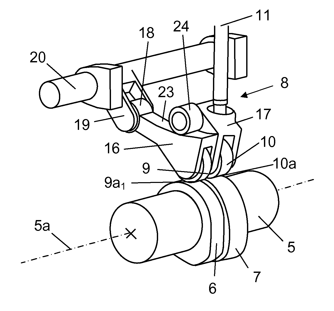
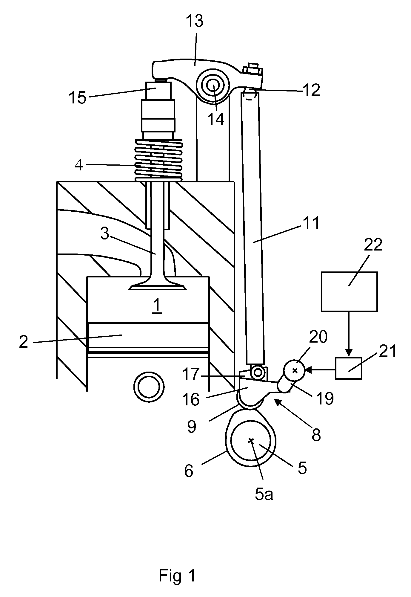
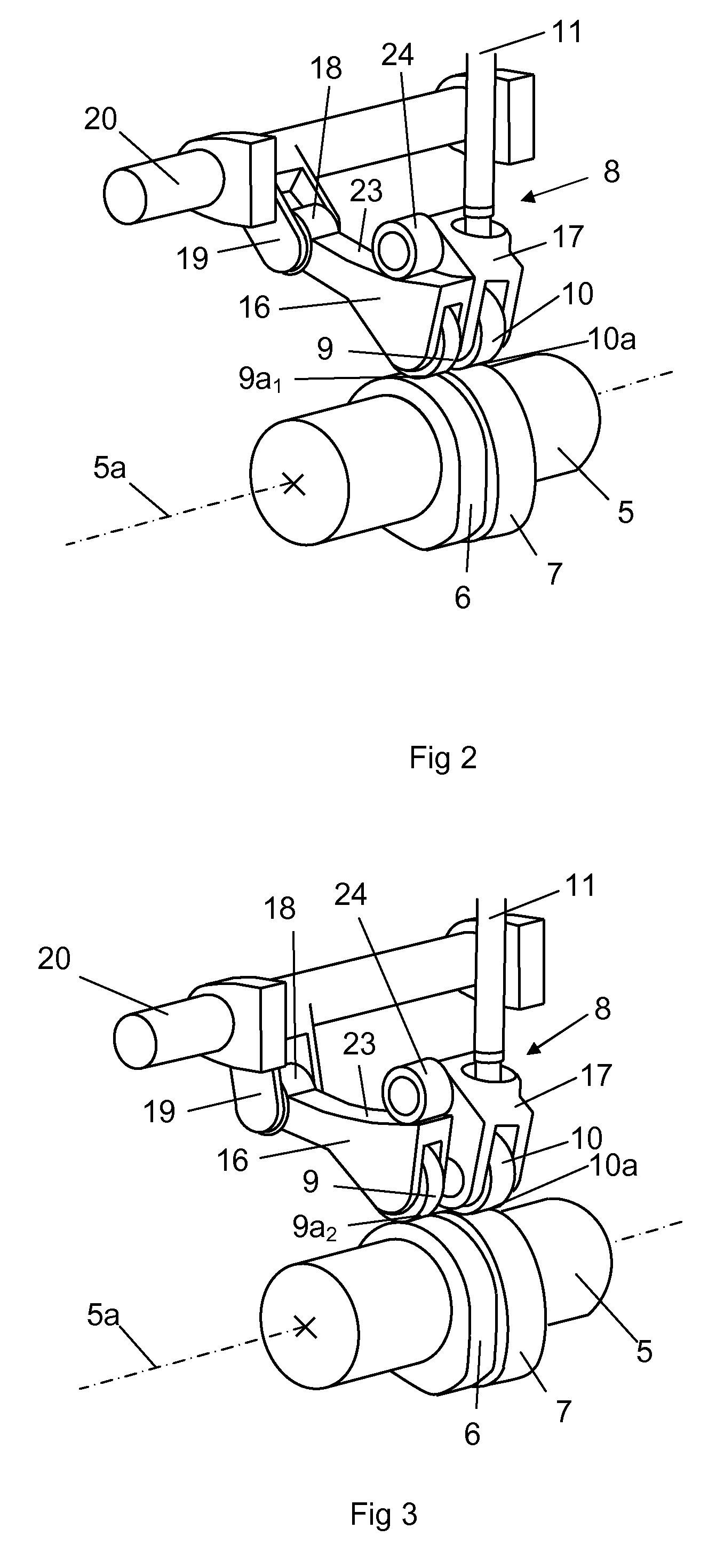
[0023]FIG. 1 depicts part of a cylinder of a combustion engine. The cylinder comprises a combustion space 1 defined by a movable piston 2. A valve 3 is visible in the cylinder. The valve 3 may be an inlet valve to control the supply of air to the combustion space 1, or an exhaust valve to control the evacuation of exhaust gases from the combustion space 1. Cylinders have in this case two inlet valves and two exhaust valves, although only one valve is visible in FIG. 1. Each of the valves 3 is connected to a valve spring 4 which endeavours to keep the valve 3 in a closed state. The combustion engine in this embodiment is provided with a low-level camshaft 5 which is rotatable at a speed related to the speed of the combustion engine. The combustion engine may alternatively be provided with one or more overhead camshafts. The camshaft 5 is rotatable about a rotational axis 5a. The camshaft 5 is provided with peripheral guide surfaces 6, 7, see FIG. 2. A cam follower 8 is adapted to bei...


PUM


Abstract

A valve lift device for a combustion engine, a camshaft (5), a first unit (16) with a first contact device (9) in contact with a guide surface on the camshaft (5), a motion-transmitting mechanism converting the lifting movement of the unit (16) to a lift of at least one valve (3) of the combustion engine. An adjusting device (20-22) allows linear movements of the first unit (16) and hence of the first contact device (9) in a plane which is perpendicular to the camshaft's rotational axis (5a) between at least a first position of contact (9a1) with the guide surface (6) and a second position of contact (9a2) with the guide surface (6).

Description

CROSS-REFERENCE TO RELATED APPLICATIONS[0001]The present application is a 35 U.S.C. §§371 national phase conversion of PCT / SE2011 / 050442, filed Apr. 12, 2011, which claims priority of Swedish Application No. 1050381-1, filed Apr. 19, 2010, the contents of which are incorporated by reference herein. The PCT International Application was published in the English language.BACKGROUND TO THE INVENTION AND PRIOR ART[0002]The present invention relates to a valve lift device for a combustion engine.[0003]The inlet valves and exhaust valves of combustion engines are usually controlled by a rotating camshaft provided with cams which serve as guide surfaces for a cam follower. The cam followers therefore undergo substantially vertical lifting movements which are converted, via suitable motion-transmitting components, to lifting movements for the inlet valves and the exhaust valves. The opening and closing movements of the inlet valves and exhaust valves take place when the pistons in the combu...

Claims


Application Information

Patent Timeline
Patent Type & Authority Patents(United States)
IPC IPC(8): F01L1/34
CPCF01L1/146F01L13/0063F01L13/0036F01L1/181F01L13/0047F01L13/0042
Inventor GUNNARSSON, NICLAS
Owner SCANIA CV AB
Why Eureka
Try Eureka