Walking splint with Anti-skid bottom

Inactive Publication Date: 2009-07-30
BROWN MEDICAL INDS
View PDF14 Cites 27 Cited by
  • Summary
  • Abstract
  • Description
  • Claims
  • Application Information

AI Technical Summary

Benefits of technology

[0016]A walking splint removably attachable to the lower leg and foot to substantially immobilize the ankle joint and provide stretching of the plantar fascia having the improved advantag

Problems solved by technology

However, none have the suspension architecture or offer the comfort, ease of use, compactability, or degrees of rotation and angulation of U.S. Pat. No. 6,267,742.
This may require walking down steps, and in

Method used


Image

  • Walking splint with Anti-skid bottom
  • Walking splint with Anti-skid bottom
  • Walking splint with Anti-skid bottom

Examples


Embodiment Construction

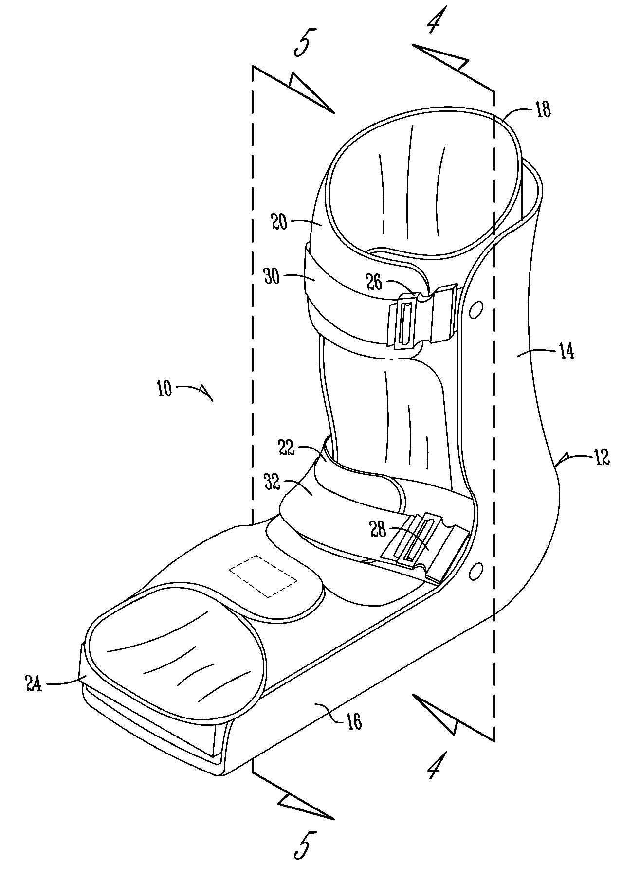
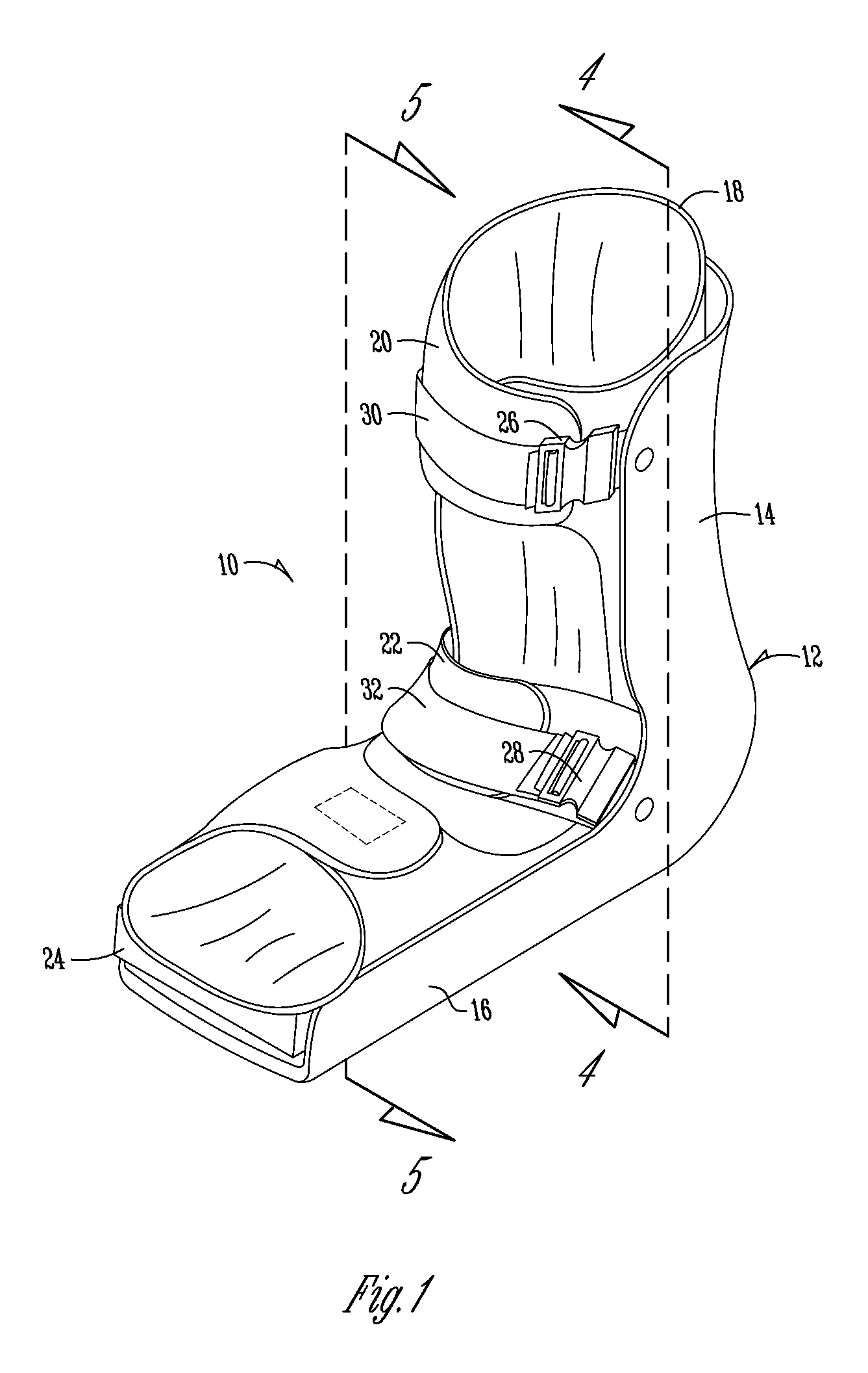
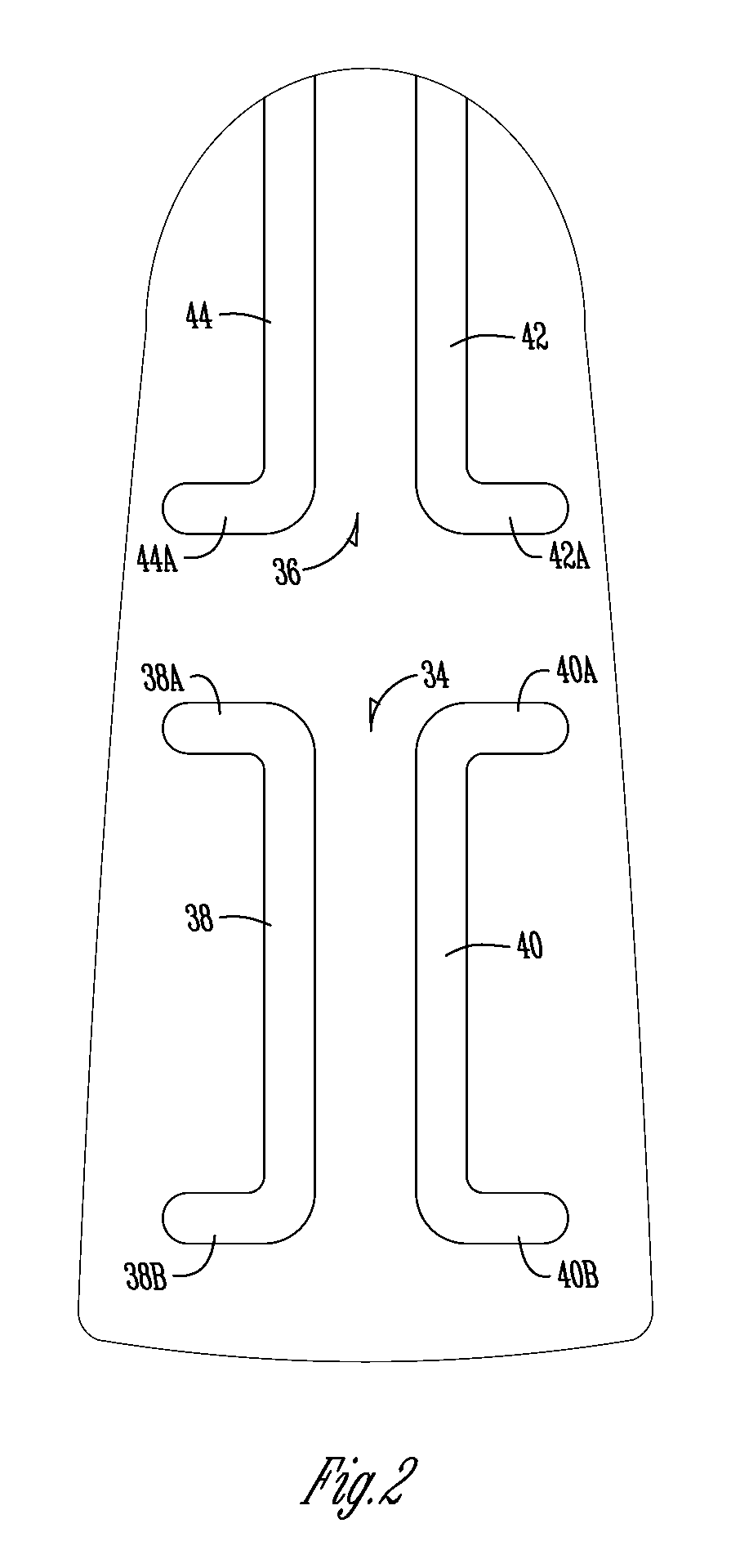
[0022]Shown in FIGS. 1-5 are a preferred form of the walking splint 10 of the present invention.

[0023]As seen best in FIGS. 1, 4 and 5, the splint 10 is comprised of a posterior rigid shell member 12 formed so that it is capable of encompassing the lower leg and foot of the patient. The posterior shell member 12 is the largest component of the splint. The posterior member 12 is generally an L-shaped shell that includes a vertical portion 14 that partially supports the posterior aspect of the leg from above the heel downwardly towards the heel and surrounds the heel to provide an underlying foot support area 16. The posterior member 14 has a heel recess formed therein to accommodate the heel of the wearer. Inserted into the shell formed by posterior shell 12 is a compressible foam wrap 18 which is comprised of a pad with a covering cloth that is useable with hook and pile fasteners such as those sold under the trademark Velcro™. Wrap 18 has strap portions 20 and 22 which may be used ...


PUM


Abstract

A walking splint removably attachable to the lower leg and foot to substantially immobilize the ankle joint and provide stretching of the plantar fascia having the improved advantage that posterior shell of the walking splint has an asymmetrically positioned anti-skid tread on the exterior of the posterior shell, preferably under both the foot area and the heel area.

Description

FIELD OF THE INVENTION[0001]The present invention relates to a walking splint to mobilize the patient while the ankle joint is immobile and stretching the Plantar Fascia.BACKGROUND OF THE INVENTION[0002]There are many reasons for orthopedic treatment that necessitate immobilization of the ankle joint and holding it to a fairly immobile position. One of the most common reasons is the common ankle sprain. Usually the treatment objective is to relieve the pain and immobilize the joint and the ligaments to promote healing of torn fibers.[0003]Another common reason for needed immobilization is plantar fasciitis. Plantar fasciitis is one of the most common causes of heel pain. This condition occurs in a wide variety of individuals. Plantar fasciitis can and does develop at any age, particularly in young athletes who put extreme exertion on their feet such as basketball and volleyball players. Many patients with plantar fasciitis also have moderate pronation; about 15% have high-arched, ri...

Claims


Application Information

Patent Timeline
IPC IPC(8): A61F5/00
CPCA61F5/0111
Inventor BROWN, IVAN E.KOUNKEL, TERYLE L.
Owner BROWN MEDICAL INDS
Why Eureka
Try Eureka