Device with a base body

a technology of a base body and a body is applied in the field of devices with a base body, which can solve the problems of increasing the stimulation threshold, cytotoxic or inflammatory action, and the device mentioned at the outset is not to be understood only in the form of electrical implants

Inactive Publication Date: 2009-07-30
NMI NATURWISSENSCHAFTLICHES & MEDIZINISCHES INST AN DER UNIV TUBINGEN
View PDF10 Cites 84 Cited by
  • Summary
  • Abstract
  • Description
  • Claims
  • Application Information

AI Technical Summary

Benefits of technology

[0023]In view of the above, it is an object of the present invention to develop the device mentioned at the outset in such a way that, with different shapes and dimensions of the electrodes, it can be brought gently into contact with the tissue in such a way that the electrode tips are brought close to the target cells within the tissue, where they can be placed in a stable position.

Problems solved by technology

However, the device mentioned at the outset is not to be understood only in the form of electrical implants, but also in the form of devices which can be used ex vivo and with which measurements or stimulation experiments can be carried out on cell aggregates, for example, as is the case in dose-finding studies for pharmacological substances or in toxicity measurements for determining maximum workplace concentrations, and in which cultured tissue is used instead of living test animals.
However, in implants with a high electrode density, for example in retinal implants, the surface of the individual electrodes is so small that, even with a porous structure, the charge transfer capacitance is not always sufficient, and instead electrochemical effects on the electrode occur that increase the stimulation thresholds and can even have a cytotoxic or inflammatory action.
The close mechanical coupling to the target cells that are to be stimulated is also limited in planar micro-electrodes, which cannot penetrate into the adjoining tissue.
This problem arises in particular in retinal implants since, for example, the lost photoreceptors or possible glial scars obstruct the close mechanical contact between the electrodes and the neurons that are to be stimulated.
As has already been mentioned at the outset, the implantation of electrodes is often followed by scarring at the interface between electrode and tissue, as a result of which the electrical properties of this interface layer alter in a disadvantageous manner.
On the one hand, the scar layer increases the electrical resistance of the contact and, on the other hand, this has the result that the distance between the electrode surface and the target cells increases.

Method used


Image

  • Device with a base body
  • Device with a base body
  • Device with a base body

Examples


Embodiment Construction

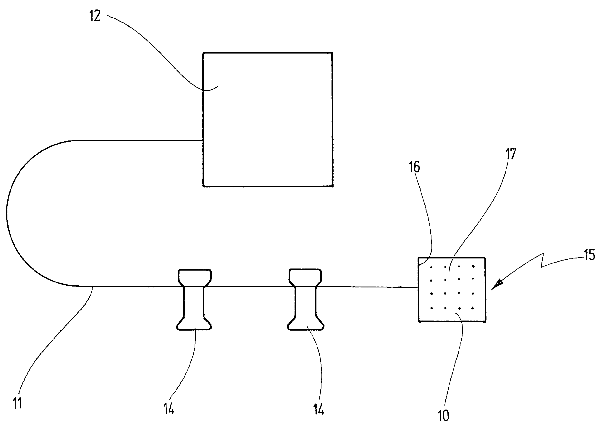
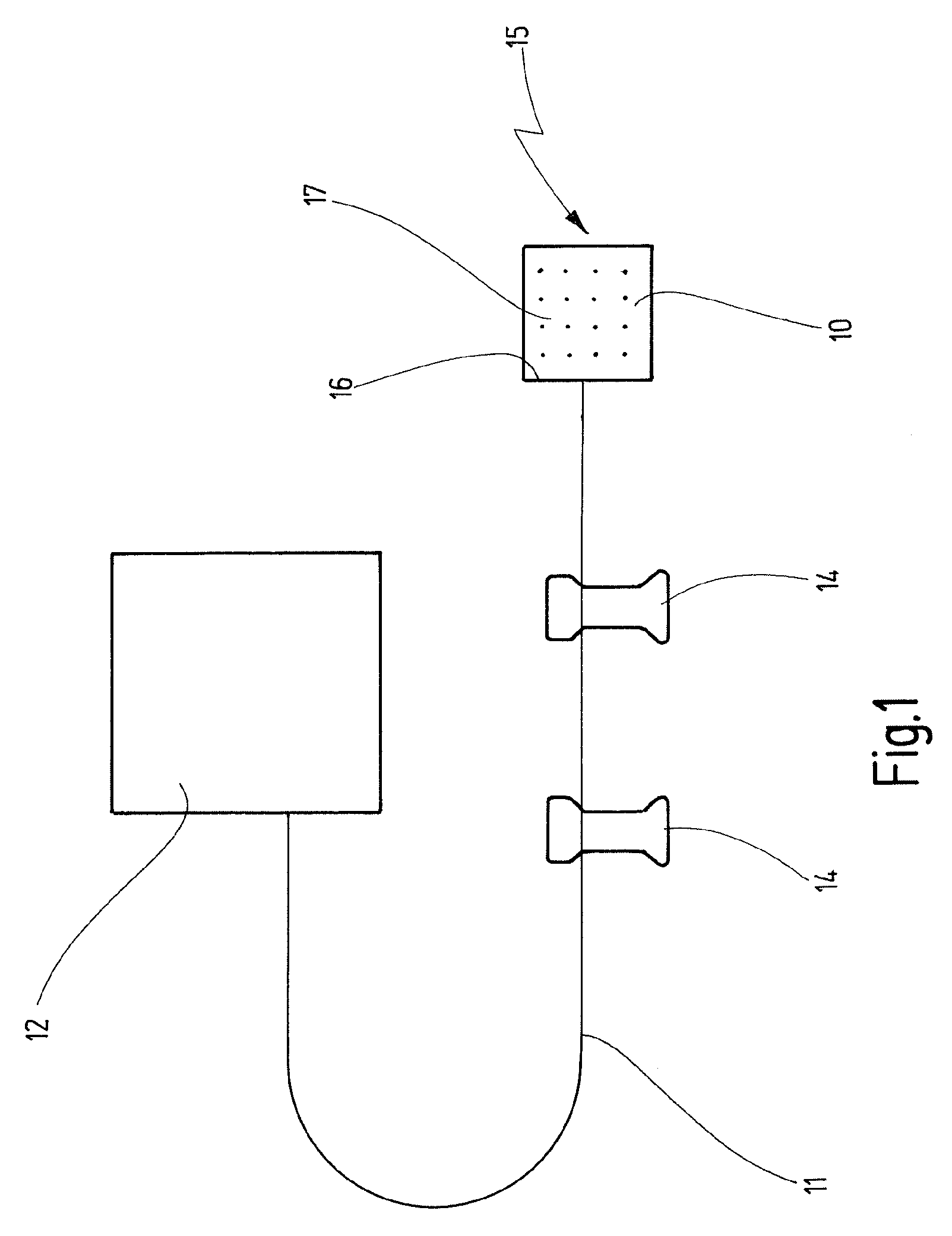
[0086]An example of the novel device is shown schematically in FIG. 1 in the form of an implantable device 10, the dimensions of which are not represented true to scale. The device 10 is connected via a cable 11 to a supply unit 12, which supplies the device 10 with electrical energy and with control signals. Securing patches 14 are provided on the cable 11 and can be used to secure the cable on the body of the person in whom the implant 10 is fitted.

[0087]The device 10 can be any desired type of implant that excites electrically excitable cells. In the case shown, it is an active retinal implant 15 which, as its base body, has a film 16 on which electrodes 17 for delivering stimulation signals to excitable cells are arranged.

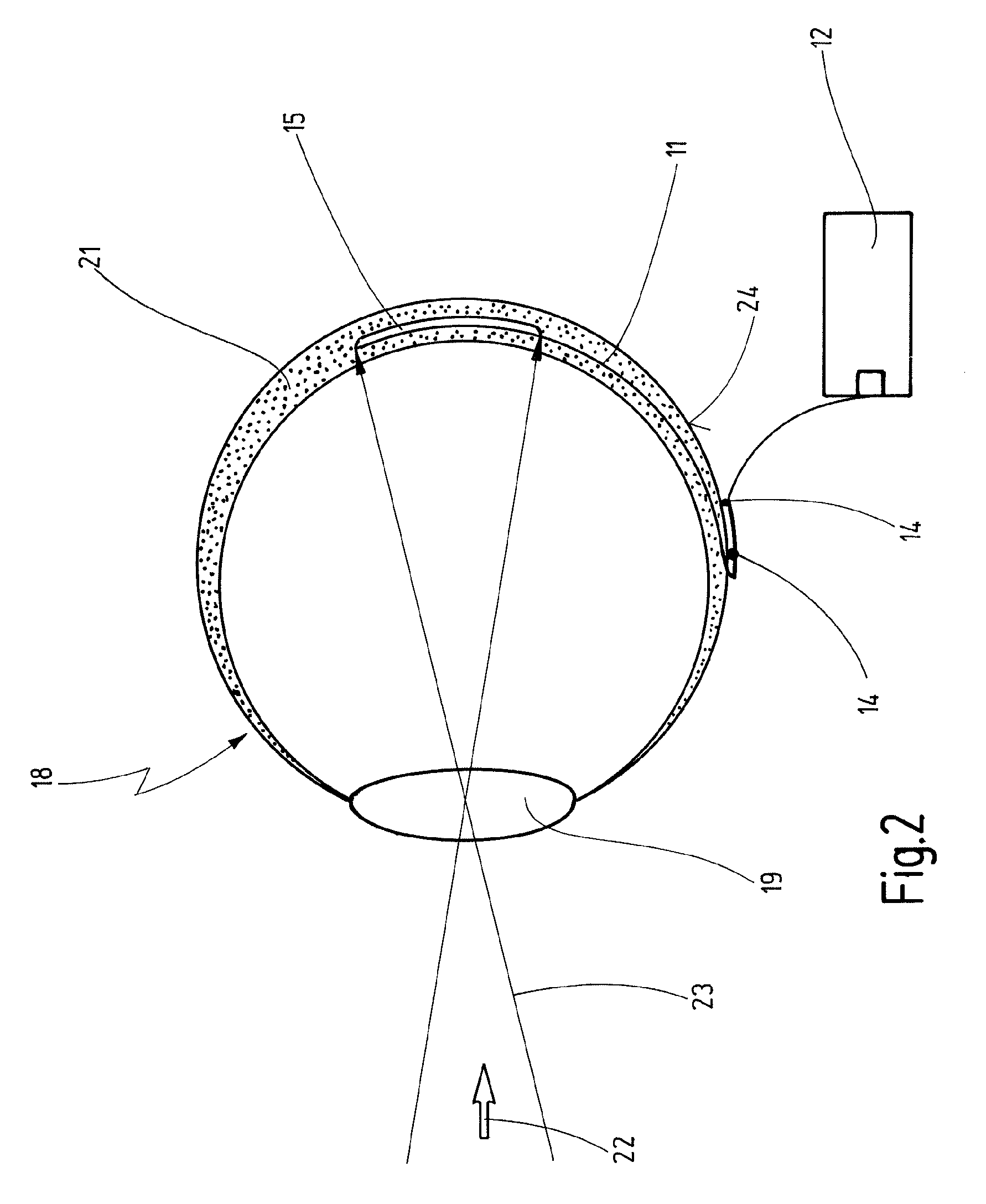
[0088]The retinal implant 15 from FIG. 1 is designed to be implanted into a human eye 18, which is depicted very schematically in FIG. 2. To keep matters simple, the figure shows only the lens 19, and the retina 21 into which the implant 15 is fitted. The impla...


PUM


Abstract

On a device 10 with a base body 32 at least one electrode 17 is arranged which serves to exchange electrical or chemical signals with surrounding tissue 34, the electrode 17 being covered by a protective layer 33 which is of such a nature that, after contact with the tissue 34, it decomposes in a defined manner and at least to such an extent that the electrode 17 comes into direct contact with the tissue 34.

Description

CROSS REFERENCE TO RELATED APPLICATIONS[0001]This is a continuation application of International Patent Application PCT / EP2007 / 008435, filed Sep. 27, 2007, designating the United States and published in English as WO 2008 / 043439, which claims priority of German patent application DE 10 2006 048 819.9, filed 10. Oct. 2006. The entire contents of these prior applications are incorporated herein by reference.BACKGROUND OF THE INVENTION[0002]1. Field of the Invention[0003]The present invention relates to a device with a base body on which base body at least one electrode is arranged, which electrode serves to exchange electrical or chemical signals with surrounding tissue and is covered by a protective layer. The invention further relates to a method for production of a device of this kind.[0004]2. Related Prior Art[0005]A device of this kind is known from EP 0 388 480 A1, for example.[0006]The known device is an implantable porous stimulation electrode on a cardiac pacemaker, in which ...

Claims


Application Information

Patent Timeline
Patent Type & Authority Applications(United States)
IPC IPC(8): A61N1/36A61N1/05
CPCA61N1/05A61N1/36046A61N1/0543
Inventor STETT, ALFREDNISCH, WILFRIED
Owner NMI NATURWISSENSCHAFTLICHES & MEDIZINISCHES INST AN DER UNIV TUBINGEN
Why Eureka
Try Eureka