

Fastener driving tool
a technology of driving tool and plunger, which is applied in the direction of manufacturing tools, stapling tools, nailing tools, etc., can solve the problems of not being able to drive the next mail, requiring a large amount of time to move the plunger for the drive, and affecting the driving feeling, so as to improve the driving feeling.
- Summary
- Abstract
- Description
- Claims
- Application Information
AI Technical Summary
Benefits of technology
Problems solved by technology
Method used
Image

Examples
Embodiment Construction
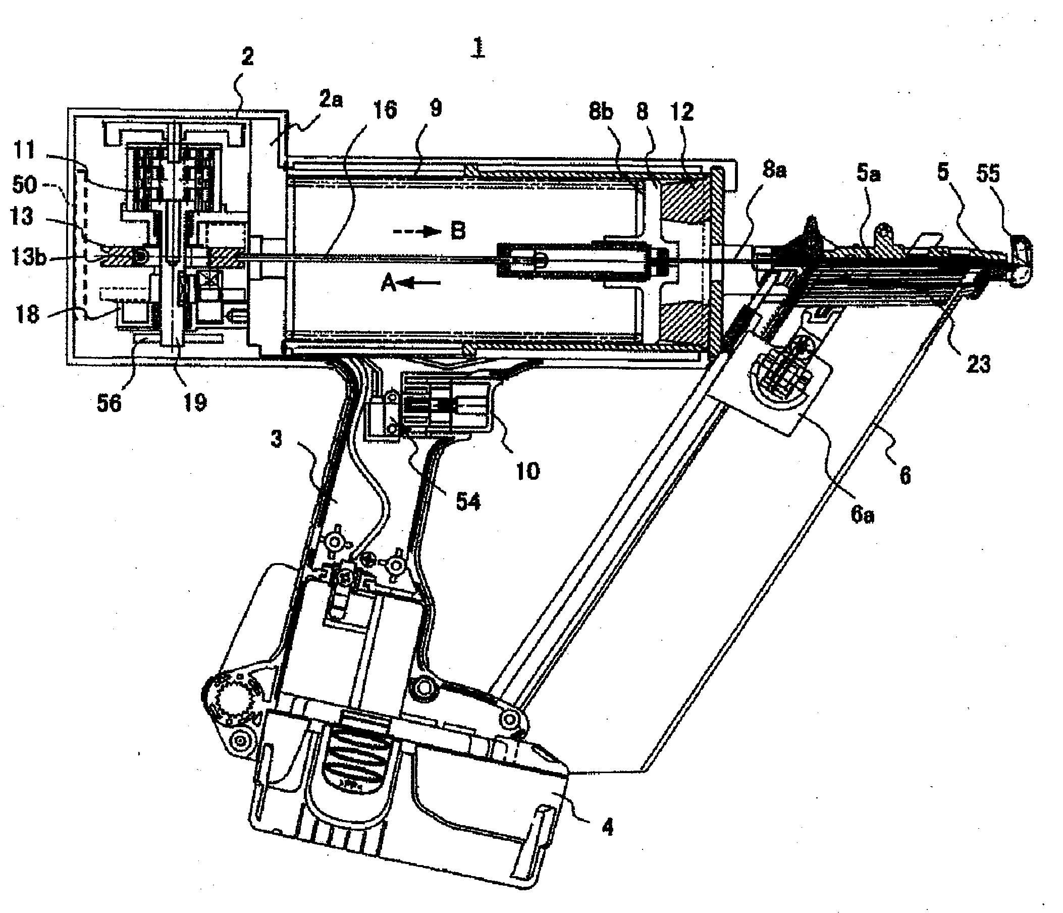
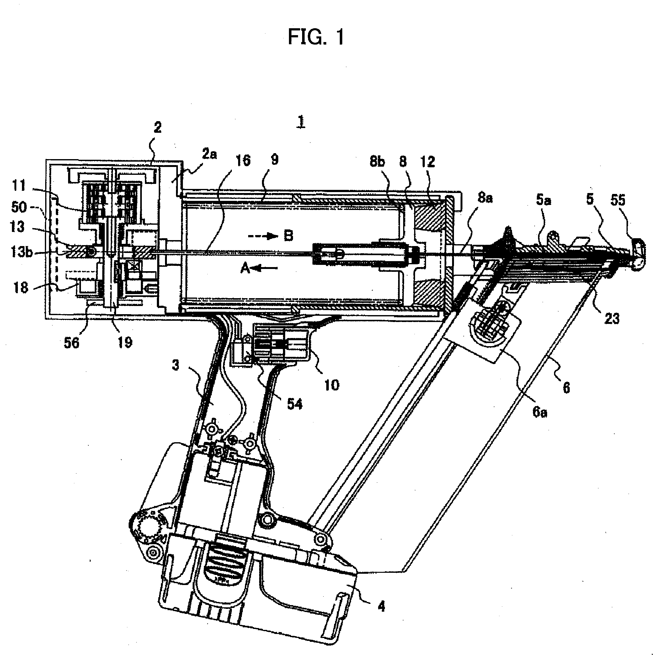
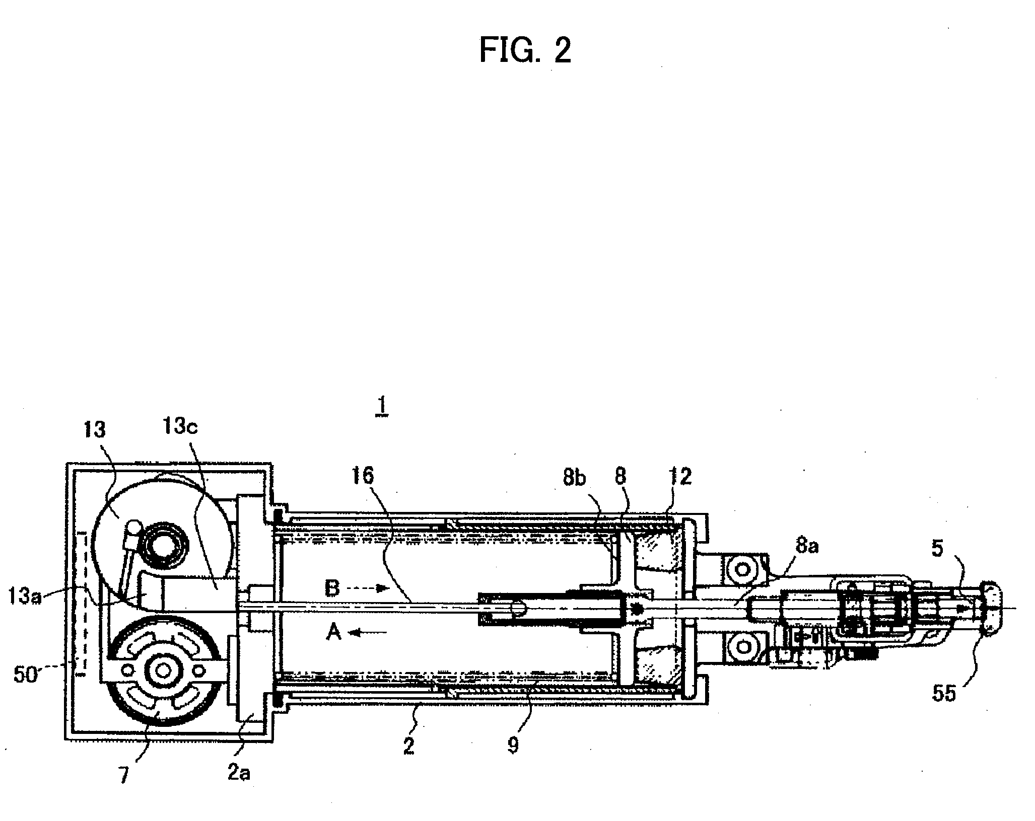
[0065]The following is an explanation with reference to the drawings of a spring-driven fastener driving tool of the embodiment of the present invention. In all of the drawings illustrating the embodiment, portions having the same function are given the same numerals and are not repeatedly described. In the following explanation of the fastener driving tool of the present invention, for convenience, the direction in which the fastener is driven is referred to as “downwards” and the opposite direction to this direction is referred to as “upwards”. This is in no way limiting with regards to special embodiments or intentions of the present invention and the present invention is by no means limited to either direction of driving the fastener.
[0066][Regarding the Assembly Configuration for the Fastener Driving Tool]
[0067]FIGS. 1 to 12 show structural views and circuit diagrams for a fastener driving tool of the embodiment. First, a description is given of the overall structure of the fas...
PUM
| Property | Measurement | Unit |
|---|---|---|
| time | aaaaa | aaaaa |
| rotation angle | aaaaa | aaaaa |
| rotation angle | aaaaa | aaaaa |
Abstract
Description
Claims
Application Information