Apparatus and method for manufacturing products from a thermoplastic mass

a technology of thermoplastic mass and apparatus, applied in the field of apparatus for manufacturing products, can solve the problems of limited wall thickness, limited product minimum and maximum size, and larger problem, and achieve the effects of low closing pressure, limited wall thickness, and simple manner

Inactive Publication Date: 2009-08-06
ECIM TECH
View PDF9 Cites 3 Cited by
  • Summary
  • Abstract
  • Description
  • Claims
  • Application Information

AI Technical Summary

Benefits of technology

[0006]The object of the invention is to provide an apparatus of the type described in the opening paragraph, wherein in a simple manner and with relatively low closing pressures, products can be manufactured having at least parts with a relatively limited wall thickness.

Problems solved by technology

It is clear that with plastics with a high viscosity and / or a low melt flow, these problems occur to a larger extent.
As a result, limitations are imposed on the minimum and maximum sizes of products, in particular on lengths of flow paths, on passage widths of such flow paths, on the duration of the injection molding cycles, on the materials to be used and on the minimum wall thicknesses of products, in particular of large, flat parts.
The danger exists that then, the plastic is not uniformly distributed, so that, for instance, a part of the material can be pressed sideways from the mold cavity before the mold cavity is completely closed.
Also, the danger exists that insufficient or, conversely, too much plastic is introduced into the mold cavity.
In this latter case, skin formation will occur between the mold halves and, moreover, it will not be possible to close the mold completely.
This leads to irregularly formed products and, moreover, to pollution of the mold.
A further disadvantage of this apparatus is that when materials are used with a low viscosity and / or with shallow mold halves, the material flows from the mold cavity before the mold halves are moved together, so that the earlier mentioned problems occur to an even larger extent.

Method used


Image

  • Apparatus and method for manufacturing products from a thermoplastic mass
  • Apparatus and method for manufacturing products from a thermoplastic mass
  • Apparatus and method for manufacturing products from a thermoplastic mass

Examples


Embodiment Construction

[0035]In this description, identical or corresponding parts have identical or corresponding reference numerals. The embodiments shown are only given by way of example and should not be taken as being limitative in any way.

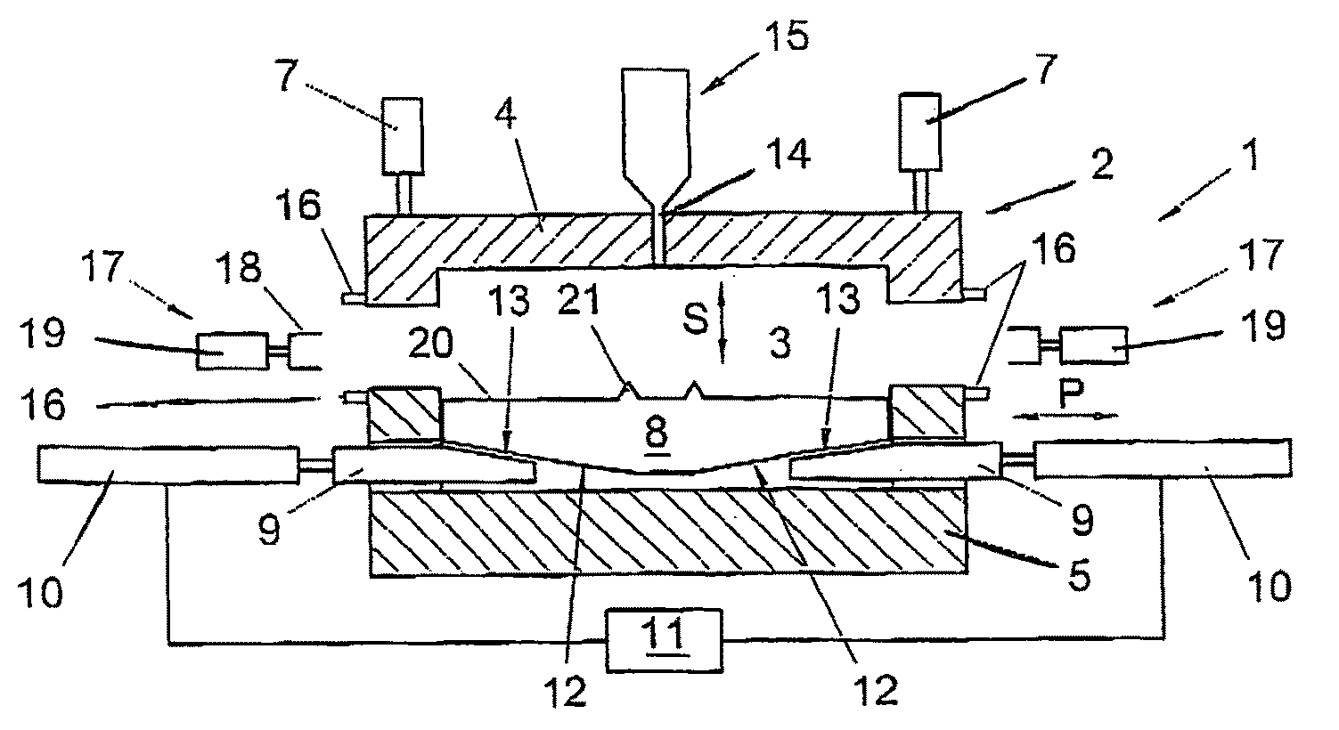
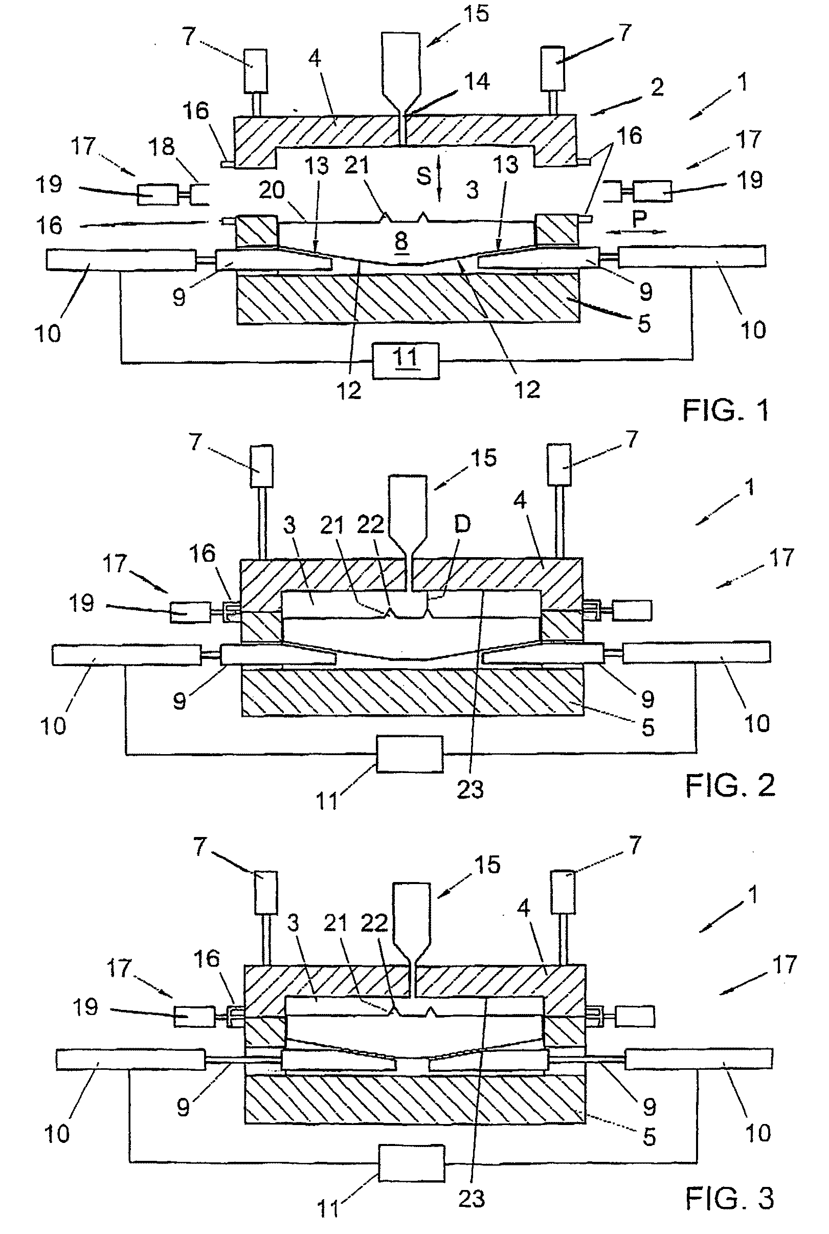
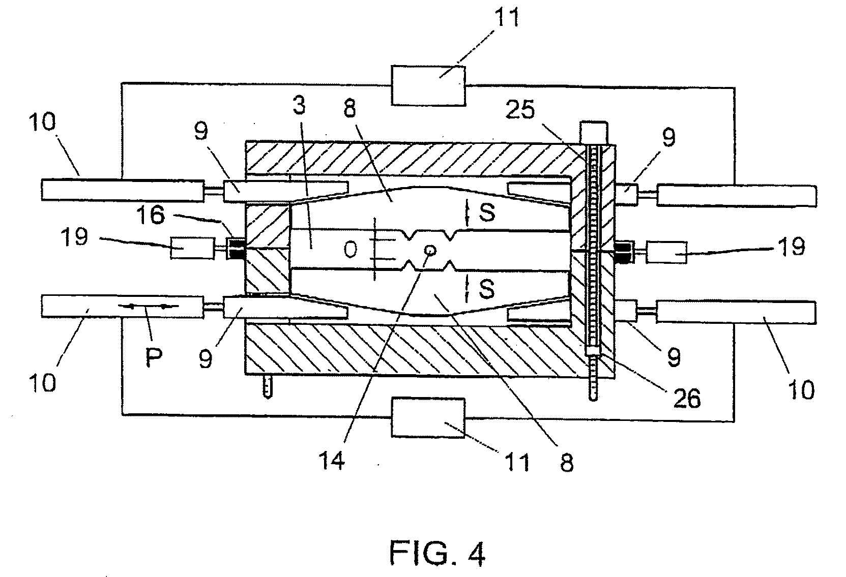
[0036]FIG. 1 shows, in cross-sectional side view, an apparatus 1 according to the invention, provided with a mold 2 with a mold cavity 3 therein. The mold comprises a first, moveable part 4 and a second, complementary part 5, fixedly arranged. The moveable part 4 is guided by suitable guides, which are not shown but can, for instance, be sliding pins, rails, guide rods or a press or the like and which are directly clear to the skilled person. The moveable part is moveable with the aid of devices suitable to that end, represented in FIGS. 1-3 as piston-cylinder assemblies 7. It is clear that this may be any suitable device, for instance also a simple press, screw means such as spindles as shown in FIG. 4, link systems or the like. These can be of relatively light de...


PUM

PropertyMeasurementUnit
pressuresaaaaaaaaaa
pressuresaaaaaaaaaa
operating pressureaaaaaaaaaa

Abstract

An apparatus for manufacturing products from material which is thermoplastically deformable, as from plastic, comprising: —a mold (2) with at least one mold cavity (3); —in the or each mold cavity (3) at least one slide (8); —movement means for moving each slide (8); —closing means for opening and closing the mold (2); —feed means for introducing, with the mold cavity (3) closed, said material in at least substantially plastic condition into the or each mold cavity; wherein the movement means (9) for moving the slide (3) are arranged for moving said slide forward at a relatively high speed relative to the movement speed of the mold parts upon opening and closing thereof, from a position at least partly retracted from the mold cavity, such that said material, as a result, is displaced in the mold cavity for obtaining the filling thereof, preferably at a speed high such that adiabatic heat development occurs in the or each mold cavity.

Description

CROSS-REFERENCE TO RELATED APPLICATIONS[0001]This application is a divisional application of U.S. application Ser. No. 10 / 507,401, filed Mar. 10, 2005, which claims the benefit of International Application No. PCT / NL2003 / 00630, filed on Sep. 3, 2003, which claims priority to NL1021421, filed Sep. 10, 2002.BACKGROUND OF THE INVENTION[0002]The invention relates to an apparatus for manufacturing products from an at least thermoplastically deformable material. Such a method is known, for instance, as injection molding.[0003]With known injection molding techniques, as a rule, the material to be formed such as plastic is heated in a plasticizing device to a temperature such that the material becomes virtually liquid, at least plastic and low-viscous, whereupon the material is introduced under high pressure into a mold cavity of an injection molding mold. In this mold cavity, the material is distributed such that the mold cavity is completely filled, whereupon the material is allowed to cu...

Claims


Application Information

Patent Timeline
Patent Type & Authority Applications(United States)
IPC IPC(8): B29C45/33B29C45/00B29C43/36B29C43/52B29C45/56
CPCB29C33/20B29C43/36B29C43/361B29C43/52B29L2031/756B29C2043/5808B29C2045/0094B29C2045/0098B29C2045/5635B29C45/561
Inventor HOOGLAND, HENDRICUS ANTONIUS
Owner ECIM TECH
Why Eureka
Try Eureka