Controller of LED lighting to control the maximum voltage of leds and the maximum voltage across current sources

Active Publication Date: 2009-08-06
SEMICON COMPONENTS IND LLC
View PDF7 Cites 43 Cited by
  • Summary
  • Abstract
  • Description
  • Claims
  • Application Information

AI Technical Summary

Benefits of technology

[0007]An objective of the invention is to provide an offline control circuit and a controller to control the maximum voltage of the LEDs and the maximum voltage across current sources.
[0008]The present invention provides a controller of LED driver. The controller includes a voltage-feedback circuit, a plurality of current sources, a detection circuit and a buffer circuit. The voltage-feedback circuit is coupled to a plurality of LEDs to sense a voltage-feedback signal for generating a voltage loop signal. The current sources are coupled to the LEDs to control the LED currents. The detection circuit senses the voltages of current sources for generating a clamp signal in response to a maximum voltage of the current sources. The buffer circuit generates a feedback signal in accordance with the voltage loop signal and the clamp signal. The voltage-feedback signal is correlated to the voltage across the LEDs. The feedback signal is coupled to control the maximum voltage of the LEDs...

Problems solved by technology

The drawback of the LED driver shown in...

Method used


Image

  • Controller of LED lighting to control the maximum voltage of leds and the maximum voltage across current sources
  • Controller of LED lighting to control the maximum voltage of leds and the maximum voltage across current sources
  • Controller of LED lighting to control the maximum voltage of leds and the maximum voltage across current sources

Examples


Embodiment Construction

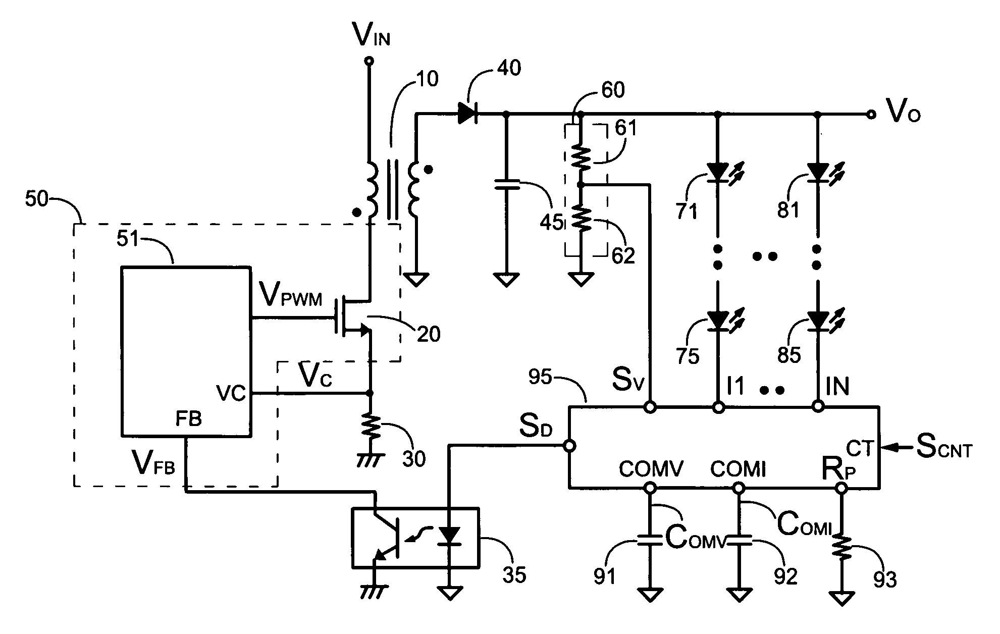
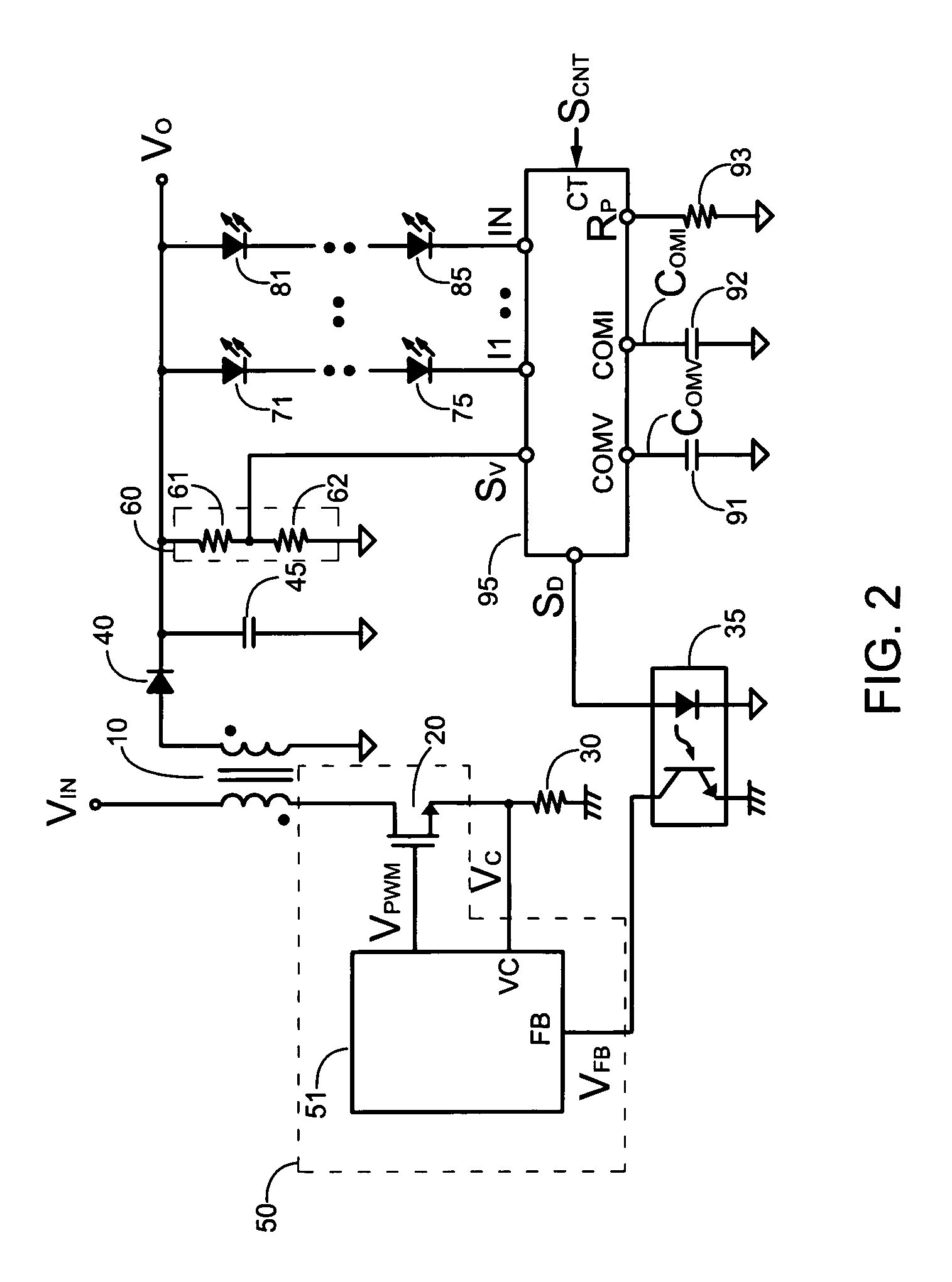
[0022]FIG. 2 shows a preferred embodiment of an offline control circuit of a LED driver in accordance with present invention. The offline control circuit includes a switching circuit50, a voltage divider 60, a first capacitor 91, a second capacitor 92 and a controller 95. LEDs 81 to 85 is connected with the LEDs 71 to 75 in parallel, and LEDs 71 to 75 and 81 to 85 are connected to the controller 95. An output voltage VO is supplied to the LEDs 71 to 75 and 81 to 85 through the controller 95. A plurality of LED currents flow into a plurality of current sources I1 to IN of the controller 95. The voltage divider 60 has at least two resistors 61 and 62 and detects the output voltage VO to generate a voltage-feedback signal SV. The controller 95 detects the voltage of the current sources I1 to IN and receives the voltage-feedback signal SV. A control terminal CT of the controller 95 receives a control signal SCNT for controlling the on / off of the current sources I1 to IN and the intensit...


PUM


Abstract

Controller of LED lighting to control the maximum voltage of LEDs and the maximum voltage across current sources is provided. A voltage-feedback circuit is coupled to the LEDs to sense a voltage-feedback signal for generating a voltage loop signal. Current sources are coupled to the LEDs to control the LED currents. A detection circuit senses the voltages of the current sources for generating a clamp signal in response to a maximum voltage of the current sources. Furthermore, a buffer circuit generates a feedback signal in accordance with the voltage loop signal and the clamp signal. The feedback signal controls the maximum voltage of the LEDs and the maximum voltage across the current sources.

Description

BACKGROUND OF THE INVENTION[0001]1. Field of the Invention[0002]The present invention relates to a LED (light emission diode) driver, and more particularly to a controller to control the maximum voltage of the LEDs and the maximum voltage across current sources.[0003]2. Description of Related Art[0004]The LED driver is utilized to control the brightness of the LED in accordance with its characteristic. The LED driver is also utilized to control the current that flow through the LED. A higher current increases intensity of the bright of the LED, but decreases the life of the LED. FIG. 1 shows a traditional offline circuit of the LED driver. The output voltage VO of the LED driver is adjusted to provide a current ILED through a resistor 79 to LEDs 71 to 75. The current ILED is shown as,ILED=VO-VF71-…-VF75R79(1)[0005]wherein the VF71 to VF75 are the forward voltage of the LEDs 71 to 75 respectively.[0006]The drawback of the LED driver shown in FIG. 1 is the variation of the current ILE...

Claims


Application Information

Patent Timeline
IPC IPC(8): H05B41/36
CPCH05B33/0815H05B33/089H05B33/0848H05B45/14H05B45/382
Inventor YANG, TA-YUNG
Owner SEMICON COMPONENTS IND LLC
Why Eureka
Try Eureka