Input power controller for AC/DC battery charging

a power controller and ac/dc technology, applied in the direction of home appliance efficiency improvement, transportation and packaging, sustainable buildings, etc., can solve the problems of high conduction loss, rise of conventional ac/dc converter control method and system, etc., and achieve the effect of optimal duty ratio

Active Publication Date: 2016-02-09
SPARQ SYST INC
View PDF3 Cites 20 Cited by
  • Summary
  • Abstract
  • Description
  • Claims
  • Application Information

AI Technical Summary

Benefits of technology

[0011]The present invention provides an input power controller for an AC / DC battery charger. The present invention directly controls the input power of a converter instead of the DC-link voltage based on the power demand from the charging curve of the battery. The controller optimally controls the boost PFC converter throughout its whole range of operation. The DC-link voltage in turn changes based on the power demand of the battery. Therefore, the downstream converter can operate with optimal duty ratio compared to the fixed DC-link voltage.
[0012]AC / DC converters used for charging the high voltage battery bank in electric vehicles from the utility mains, generally, consist of two stages: (1) a power factor correction (PFC) AC / DC boost converter to reduce the input current harmonics injected to the grid and convert the input AC voltage to an intermediate DC voltage (DC-Bus voltage), and (2) an isolated DC / DC converter for providing high frequency galvanic isolation. A control approach of adjusting the input power of the PFC stage so that the output voltage (DC-link) of the input AC / DC stage is adjusted based on the amount of power required to charge the high energy battery, is described herein. The present invention controls the input power of the PFC instead of the DC-bus voltage. Therefore, a very fast response compared to the conventional sluggish voltage loop can be achieved. Also, having different DC-bus voltages for different output load conditions allows the DC / DC converter to work with an optimal duty cycle for a whole range of load variations. This results in better overall efficiency and superior performance over conventional systems.

Problems solved by technology

However, at small duty-ratios, to maintain zero voltage switching (ZVS), the amount of reactive current should be increased, but that in turn leads to higher conduction losses.
Another major drawback of the conventional AC / DC converters is the control method and system.
Otherwise, the second harmonic would modulate the control signal at the controller output, giving rise to a third harmonic distortion of the input current.
In addition, such a low bandwidth voltage control loop gives rise to a very sluggish transient response or high overshoots and undershoots in the DC-bus voltage during load transients.
This causes unwanted over designing of downstream converters, which affects their efficiency and overall cost.
Thus, linear PI regulators are not able to optimally perform for the whole operating range.
In addition, there is another main challenge in the voltage control loop of the converter due to the presence of second harmonic ripple at the output voltage (DC-link).
Therefore, the transient response of the converter is very poor and the system usually has marginal stability against severe load changes.
Precise tuning of the comb filter and synchronizing of the coarse sampler are usually challenging and offset the advantages of the existing techniques.
In addition, complicated digital algorithms reduce the reliability of the converter.
From the above discussion, it can be concluded that the necessity of filtering the second harmonic ripple is the prime cause of sluggish response of a conventional control methods for a PFC AC / DC boost converter.

Method used


Image

  • Input power controller for AC/DC battery charging
  • Input power controller for AC/DC battery charging
  • Input power controller for AC/DC battery charging

Examples


Embodiment Construction

[0032]The terms “coupled” and “connected”, along with their derivatives, may be used herein. It should be understood that these terms are not intended as synonyms for each other. Rather, in particular embodiments, “connected” may be used to indicate that two or more elements are in direct physical or electrical contact with each other. “Coupled” may be used to indicate that two or more elements are in either direct or indirect (with other intervening elements between them) physical or electrical contact with each other, or that the two or more elements co-operate or interact with each other (e.g. as in a cause and effect relationship).

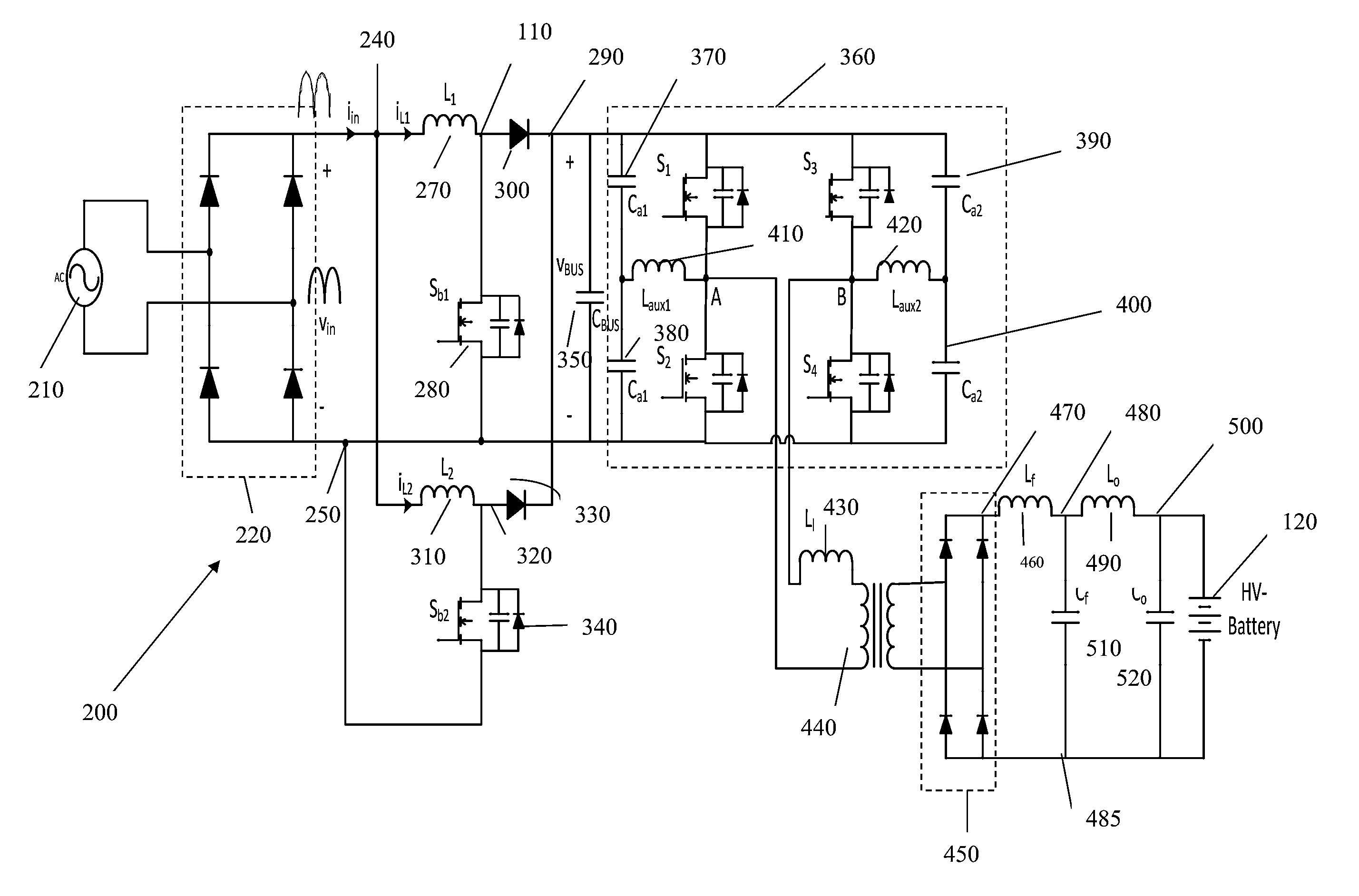
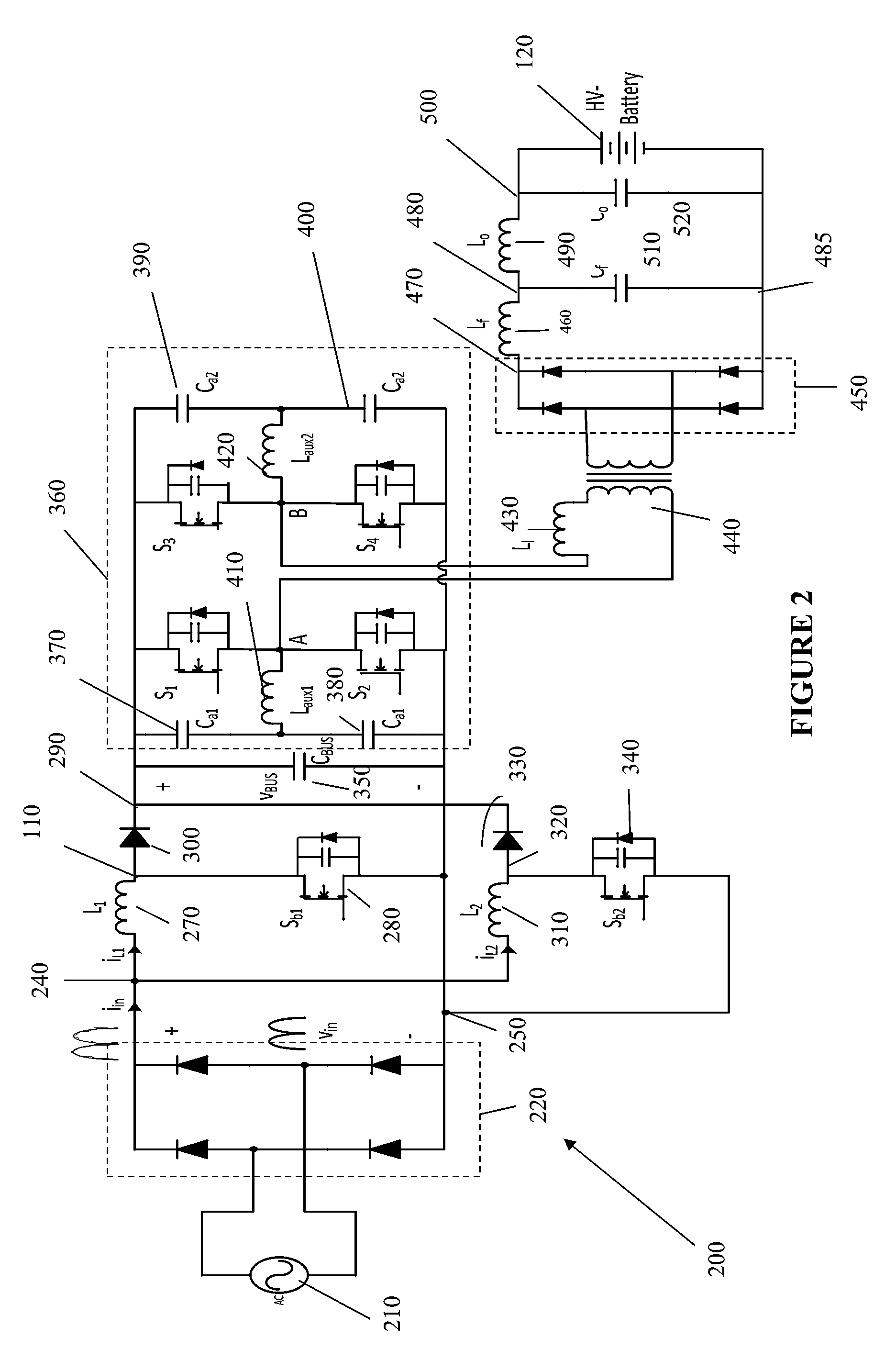
[0033]The present invention provides a controller that regulates the input power of a PFC converter, instead of the DC-bus voltage. The controller mainly adjusts the amplitude of the input current reference and hence the DC-bus voltage, based on the power demand.

[0034]Nonlinear controllers can optimize the performance of the PFC converter for a wide ra...


PUM


Abstract

A control approach of adjusting the input power of a power factor correction (PFC) stage so that the output voltage (DC-link) of the input AC / DC stage to an intermediate DC voltage (DC-Bus voltage) is adjusted based on the amount of power required to charge a high energy battery is disclosed. The present invention controls the input power of the PFC instead of the DC-bus voltage as is common in conventional methods. Therefore, a very fast response compared to the conventional sluggish voltage loop can be achieved. Also, having different DC-bus voltages for different output load conditions allows the DC / DC converter to work with an optimal duty cycle for a whole range of load variations.

Description

FIELD OF THE INVENTION[0001]The present invention relates to control systems to boost PFC AC / DC converters. More specifically, the present invention relates to methods, circuits, and devices for controlling AC / DC converters. In particular, this invention relates to Electric Vehicle (EV) power conditioning systems, which utilize an AC / DC converter to charge the high voltage battery (traction battery).BACKGROUND TO THE INVENTION[0002]Power conversion systems in Electric Vehicles (EVs) usually utilize a high energy battery pack to store energy for the electric traction system. This high energy battery pack is typically charged by a utility for an alternating current (AC) outlet. The energy conversion during the battery charging is performed by an AC / DC (direct current) converter. Such AC / DC converters, which are used to charge the high-energy battery, usually consist of two stages: (1) an input Power Factor Correction (PFC) with AC / DC conversion stage and (2) a DC / DC converter for batt...

Claims


Application Information

Patent Timeline
Patent Type & Authority Patents(United States)
IPC IPC(8): H02J7/00H02M1/10H02J7/02H02M1/42
CPCH02J7/022H02M1/10H02M1/4225Y02B40/90Y02B70/126H02J7/02H02J2207/20Y02B40/00Y02B70/10
Inventor PAHLEVANINEZHAD, MAJIDJAIN, PRAVEEN
Owner SPARQ SYST INC
Why Eureka
Try Eureka