Wireless non-radiative energy transfer

a non-radiative energy and wireless technology, applied in waveguide devices, resonance antennas, transportation and packaging, etc., can solve the problems of not being suitable for such energy transfer, omni-directional antenna radiative modes, and little success in efforts

Active Publication Date: 2009-08-06
MASSACHUSETTS INST OF TECH
View PDF99 Cites 434 Cited by
  • Summary
  • Abstract
  • Description
  • Claims
  • Application Information

AI Technical Summary

Problems solved by technology

These efforts appear to have met with little, if any, success.
Radiative modes of omni-directional antennas, which work very well for information transfer, are not suitable for such energy transfer, because a vast majority of energy is wasted into free space.
Directed radiation modes, using lasers or highly-directional antennas, can be efficiently used for energy transfer, even for long distances (transfer distance LTRANSLDEV, where LDEV is the characteristic size of the device), but require existence of an uninterruptible line-of-sight and a complicated tracking system in the case of mobile objects.

Method used


Image

  • Wireless non-radiative energy transfer
  • Wireless non-radiative energy transfer
  • Wireless non-radiative energy transfer

Examples


Embodiment Construction

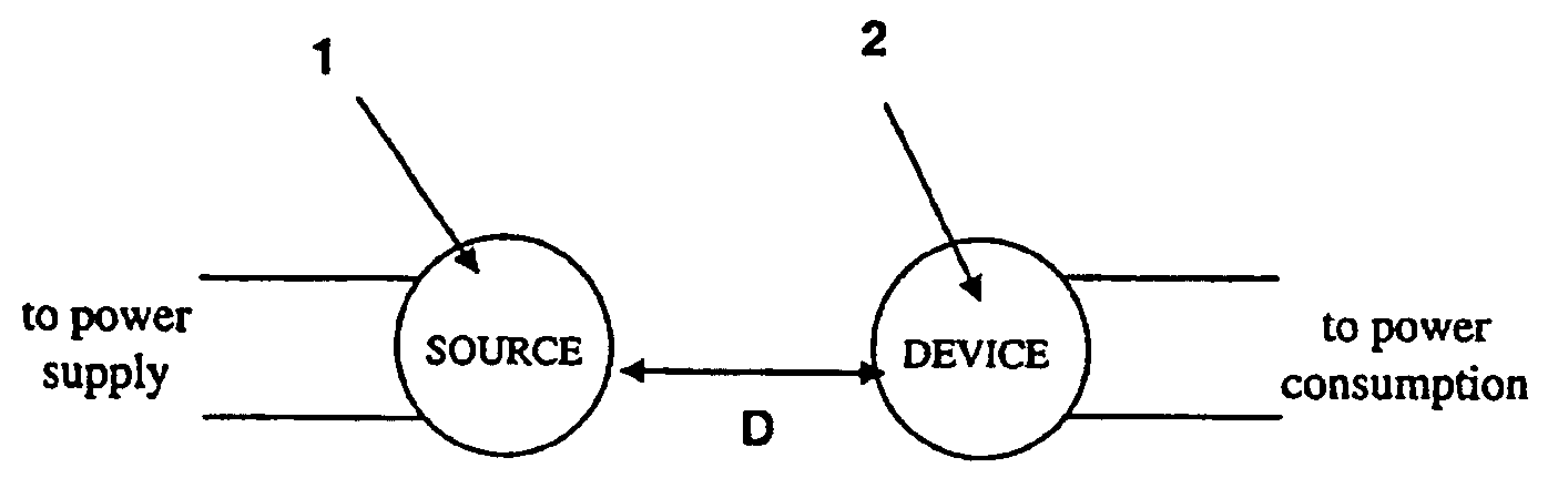
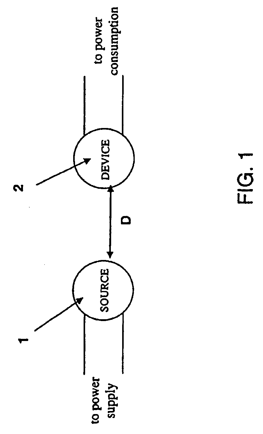
[0034]In contrast to the currently existing schemes, the invention provides the feasibility of using long-lived oscillatory resonant electromagnetic modes, with localized slowly evanescent field patterns, for wireless non-radiative energy transfer. The basis of this technique is that two same-frequency resonant objects tend to couple, while interacting weakly with other off-resonant environmental objects. The purpose of the invention is to quantify this mechanism using specific examples, namely quantitatively address the following questions: up to which distances can such a scheme be efficient and how sensitive is it to external perturbations. Detailed theoretical and numerical analysis show that a mid-range (LTRANS≈few*LDEV) wireless energy-exchange can actually be achieved, while suffering only modest transfer and dissipation of energy into other off-resonant objects.

[0035]The omnidirectional but stationary (non-lossy) nature of the near field makes this mechanism suitable for mob...


PUM


Abstract

The electromagnetic energy transfer device includes a first resonator structure receiving energy from an external power supply. The first resonator structure has a first Q-factor. A second resonator structure is positioned distal from the first resonator structure, and supplies useful working power to an external load. The second resonator structure has a second Q-factor. The distance between the two resonators can be larger than the characteristic size of each resonator. Non-radiative energy transfer between the first resonator structure and the second resonator structure is mediated through coupling of their resonant-field evanescent tails.

Description

CROSS-REFERENCE TO RELATED APPLICATIONS[0001]This application is a continuation and claims the benefit of priority under 35 USC § 120 to U.S. application Ser. No. 11 / 481,077 filed Jul. 5, 2006, which claims priority under 35 USC § 119(e) to U.S. provisional application Ser. No. 60 / 698,442 filed Jul. 12, 2005. The contents of the prior applications mentioned above are incorporated herein by reference in their entirety.STATEMENT AS TO FEDERALLY FUNDED RESEARCH[0002]This invention was made with government support awarded by the National Science Foundation under Grant No. DMR-0213282. The government has certain rights in this invention.BACKGROUND OF THE INVENTION[0003]The invention relates to the field of oscillatory resonant electromagnetic modes, and in particular to oscillatory resonant electromagnetic modes, with localized slowly evanescent field patterns, for wireless non-radiative energy transfer.[0004]In the early days of electromagnetism, before the electrical-wire grid was depl...

Claims


Application Information

Patent Timeline
Patent Type & Authority Applications(United States)
IPC IPC(8): H01P1/20H01P7/00
CPCB60L11/182H01Q9/04H02J5/005Y02T90/14Y02T10/7005Y02T10/7088Y02T90/122H02J17/00H02J50/12B60L53/126H02J50/40H02M3/01H02M1/0064H04B5/0037Y02T10/70Y02T10/7072H01P7/00Y02T90/12H01F38/14
Inventor JOANNOPOULOS, JOHN DKARALIS, ARISTEIDISSOLJACIC, MARIN
Owner MASSACHUSETTS INST OF TECH
Why Eureka
Try Eureka