Stereolithography apparatus
a technology of stereolithography and apparatus, which is applied in the field of stereolithography apparatus, can solve the problems of preventing improvement in lamination precision and not being able to ignore warpage, and achieve the effect of improving lamination precision and high precision
- Summary
- Abstract
- Description
- Claims
- Application Information
AI Technical Summary
Benefits of technology
Problems solved by technology
Method used
Image

Examples
first embodiment
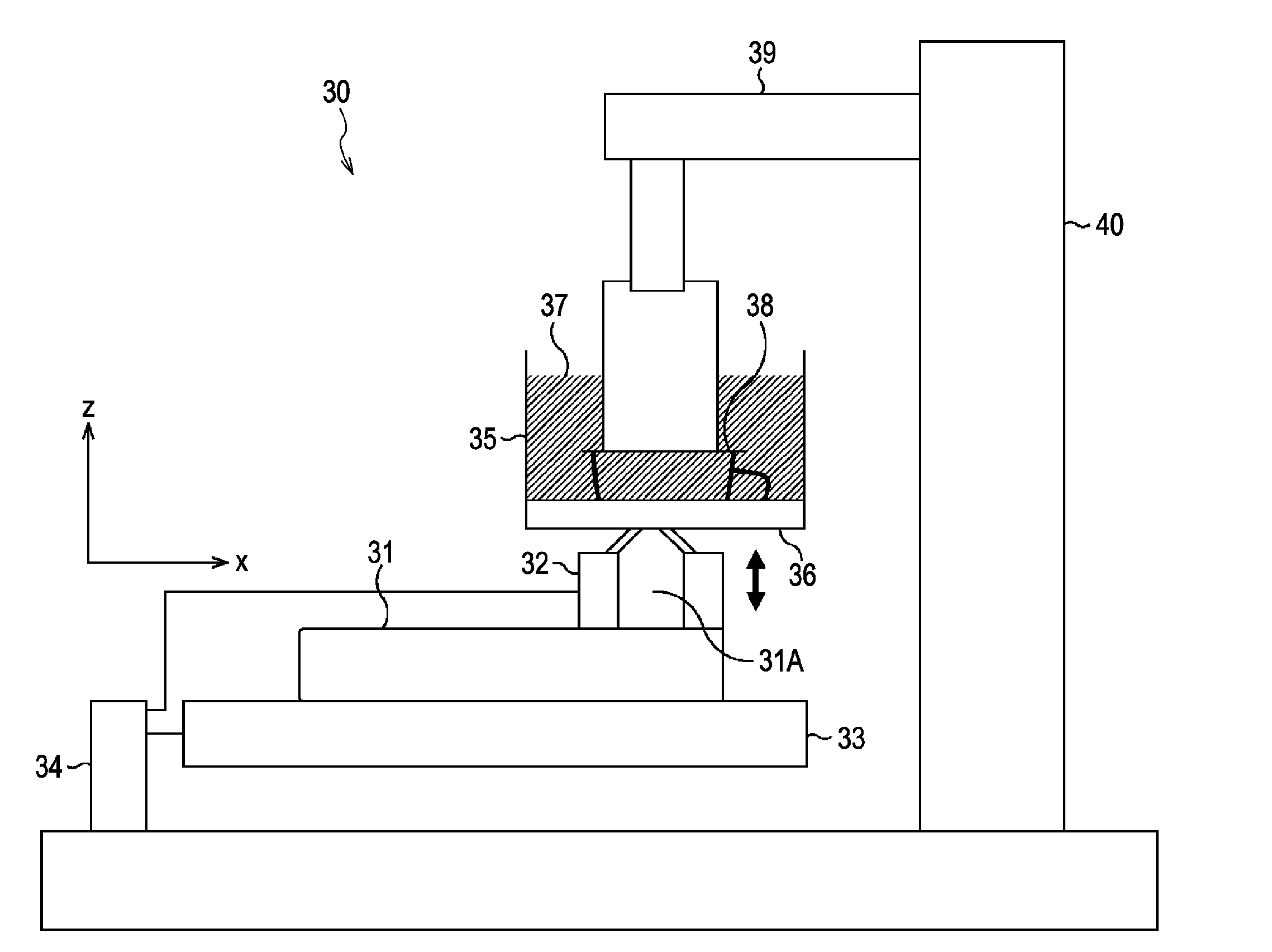
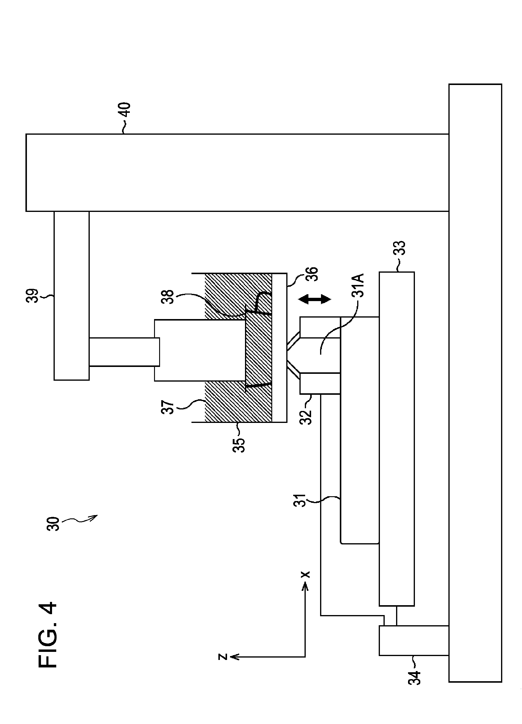
[0041]FIG. 4 illustrates the external configuration of a stereolithography apparatus according to the present invention.
[0042]A stereolithography apparatus 30, which is shown in FIG. 4, includes an optical system 31 that has an objective lens 31A, a position constraining mechanism 32, an XY stage 33, a driving unit 34, a container 35, a glass window 36, UV-curable resin 37 such as liquid resin, a Z stage 38, an arm 39, and a driving unit 40.
[0043]The stereolithography apparatus 30 carries out stereolithography according to the constrained surface method by constraining the fluid surface of the UV-curable resin 37 in the container 35 with the glass window 36 and irradiating the fluid surface of the UV-curable resin 37 with UV light through the glass window 36 in accordance with data about the three-dimensional shape of the three-dimensional model sliced into layers of a predetermined thickness in the lamination direction (hereinafter referred to as “sectional data”).
[0044]The optical...
second embodiment
[0140]FIG. 14 illustrates a stereolithography apparatus according to the present invention.
[0141]A stereolithography apparatus 150, which is shown in FIG. 14, includes an optical system 31 that has an objective lens 31A, a position constraining mechanism 32, an XY stage 33, a driving unit 34, a container 35, a glass window 36, UV-curable resin 37, a Z stage 38, an arm 39, a driving unit 40, and a pressure detector 151. The stereolithography apparatus 150 determines the fabrication reference position depending on a change in pressure applied to the Z stage 38.
[0142]In FIG. 14, components that are the same as those shown in FIG. 4 will be represented by the same reference numerals, and descriptions thereof are not repeated.
[0143]The pressure detector 151 shown in FIG. 14 is constructed of, for example, a load cell and is mounted on the Z stage 38. The pressure detector 151 detects pressure applied to the Z stage 38 and inputs the detected result to a control device 170 (FIG. 15), desc...
third embodiment
[0164]FIG. 17 illustrates a stereolithography apparatus according to the present invention.
[0165]A stereolithography apparatus 200, which is shown in FIG. 17, includes an optical system 31 that has an objective lens 31A, a position constraining mechanism 32, an XY stage 33, a driving unit 34, a container 35, a glass window 36, UV-curable resin 37 such as liquid resin, a Z stage 38, an arm 39, and a pressure detector 151, a position measuring mechanism 201, and a driving unit 202. The stereolithography apparatus 200 measures the position of the Z stage 38 from the fabrication reference position in the Z direction and moves the Z stage 38 on the basis of this position.
[0166]In FIG. 17, components that are the same as those shown in FIGS. 4 and 14 will be represented by the same reference numerals, and descriptions thereof are not repeated.
[0167]The position measuring mechanism 201 shown in FIG. 17 includes a laser distance meter and an electric micrometer. Setting the position of a su...
PUM
| Property | Measurement | Unit |
|---|---|---|
| Force | aaaaa | aaaaa |
| Pressure | aaaaa | aaaaa |
| Distance | aaaaa | aaaaa |
Abstract
Description
Claims
Application Information
 - R&D Engineer
- R&D Manager
- IP Professional
- Industry Leading Data Capabilities
- Powerful AI technology
- Patent DNA Extraction
Browse by: Latest US Patents, China's latest patents, Technical Efficacy Thesaurus, Application Domain, Technology Topic.
© 2024 PatSnap. All rights reserved.Legal|Privacy policy|Modern Slavery Act Transparency Statement|Sitemap