Latching system

Inactive Publication Date: 2009-08-13
FIN QUIVER
View PDF29 Cites 29 Cited by
  • Summary
  • Abstract
  • Description
  • Claims
  • Application Information

AI Technical Summary

Benefits of technology

[0028]In another embodiment, an attachment device, having a device receptacle configured to receive a bottom portion of a cleat device, the device receptacle including an inner cavity, or detent, configured to securely lock and prevent rotation of the cleat device. A cleat device having a top portion configured to provide traction, including a opening extending fr

Problems solved by technology

The screw method may be quite time consuming for the watercraft user to practice.
Additionally, screw and snap mechanisms may necessitate the use of multiple moving parts, any of which are subject to rusting, failure, and stress fatigue.
Toe and heel locking mechanisms are prone to failure, as the locking forces are horizontal to the bottom plane of the watercraft.
The reason this is undesirable is that in many watercraft situations a user might encounter such horizontal forces from the environment, for example, the watercraft fins could be exposed to such horizontal forces from contact with kelp, rocks, ropes, wood, sand, other watercraft, etc., and

Method used


Image

  • Latching system
  • Latching system
  • Latching system

Examples


Embodiment Construction

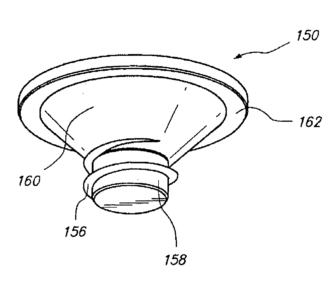
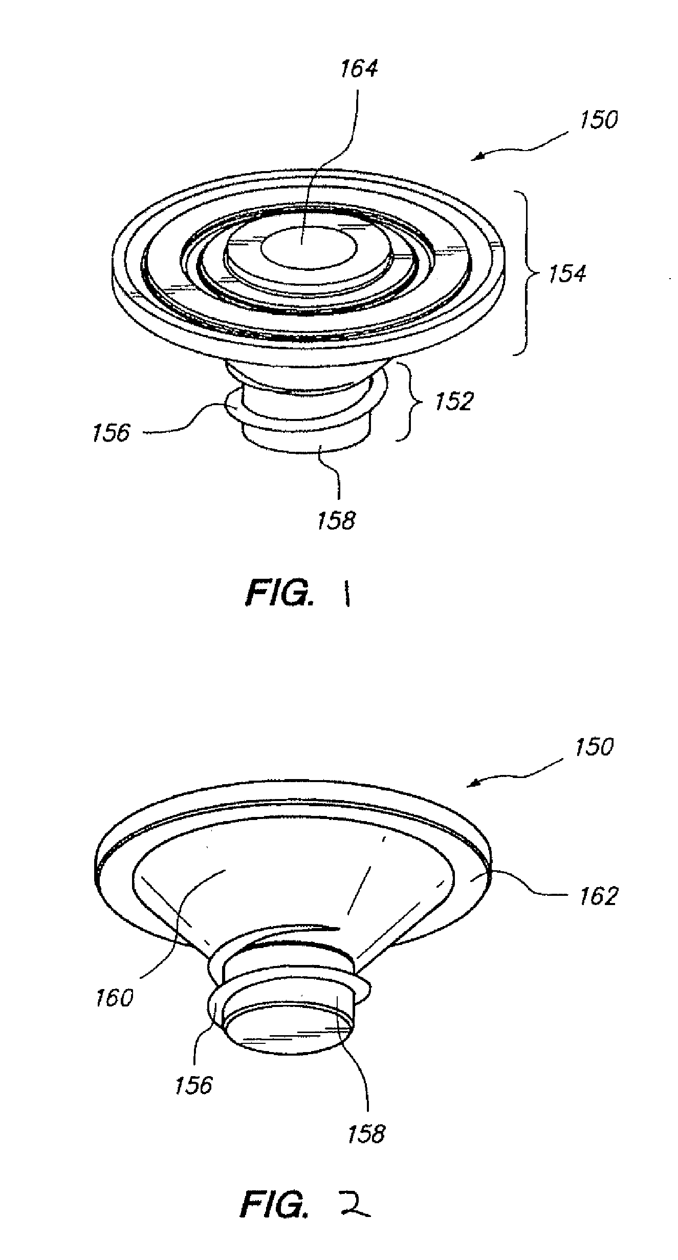
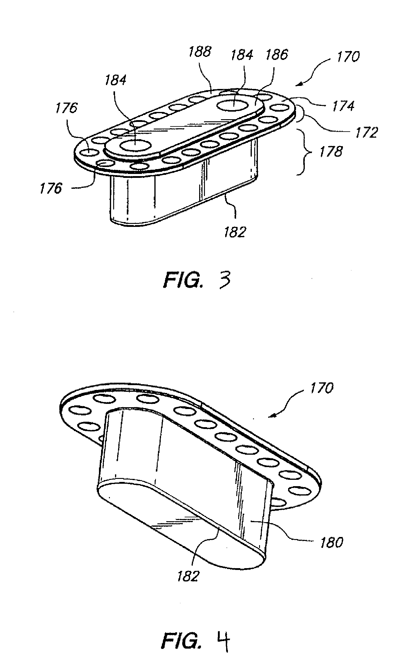
[0075]Embodiments disclosed herein relate to attachment methods and devices that utilize locking forces to securely attach a device to an object yet facilitate simple and easy detachability. The attachment methods and devices disclosed herein are applicable to a wide range of objects and devices. As discussed below, the attachment methods and devices disclosed herein can be advantageously used to couple a device to an object, wherein the device extends vertically from the object when attached, and is likely to encounter horizontal forces when attached to the object. For example, the attachment mechanisms disclosed herein can be used to attach a fin to a surfboard or other watercraft, a cleat to a shoe, a wheel truck to a rollerskate, rollerblade, or skateboard deck, a blade to an ice skate, components of components of furniture, or various other device / object pairs.

[0076]As discussed below, some embodiments disclosed herein relate to attachment devices and methods that utilize sprin...


PUM

PropertyMeasurementUnit
Angleaaaaaaaaaa
Forceaaaaaaaaaa
Angleaaaaaaaaaa

Abstract

Devices and methods based upon the concept of a split ring having certain multiple interior angles to engage a stem or post having annular ring(s) with angular geometries that are complimentary to those of the split ring. The disclosure provides designs for a wide range of insertion and desertion forces between latch engagement stems and latch engagement bodies. Changes to insertion contact angles and contact area on engagement stems and corresponding changes to insertion contact angles and engagement areas on engagement bodies can significantly modify insertion forces required to engage various devices. Similarly, changes in degrees of angle between desertion angles and contact areas on engagement stems with corresponding changes in desertion angles and contact areas on engagement bodies will significantly modify the total desertion forces required to disengage various devices. Accordingly, the instant latching mechanism provides insertion and desertion forces that can be controlled independently of each other.

Description

CROSS-REFERENCE TO RELATED APPLICATIONS[0001]This application is a continuation-in-part of U.S. patent application Ser. No. 12 / 168,809, filed Jul. 7, 2008, entitled “RELEASABLE LOCKING MECHANISM,” which, in turn, is a continuation-in-part of U.S. patent application Ser. No. 11 / 955,295, filed Dec. 12, 2007, entitled “RELEASABLE SPRING-LOCKING MECHANISM FOR RAPID WATERCRAFT FIN ATTACHMENT,” which in turn is a continuation-in-part of U.S. patent application Ser. No. 11 / 655,651, filed Jan. 19, 2007, entitled “SURFBOARD MANUFACTURING APPARATUS,” which claims the benefit of U.S. Provisional Patent Application No. 60 / 760,855, filed Jan. 20, 2006. Each of these applications is herein incorporated by reference in its entirety.BACKGROUND[0002]1. Field of the Invention[0003]Provided herein are mechanisms whereby a locking force is used to secure a device to another object.[0004]2. Description of the Related Art[0005]Users of watercraft boards generally only have two methods of securing fins to...

Claims


Application Information

Patent Timeline
IPC IPC(8): F16B35/02A44B21/00B25B27/00A44B99/00
CPCA43C15/161A63C17/01A63C17/017B63B35/7909B63B35/793Y10T24/45984Y10T403/7037Y10T24/45262Y10T29/53943Y10T29/4995F16B21/18B63B32/57B63B32/66F16B21/07A43C15/16F16B2/14
Inventor KOELLING, FREDSUBRAMANYAM, VENUGOPAL
Owner FIN QUIVER
Why Eureka
Try Eureka