
Ballistic reticle and riflescope for projectile weapon aiming system

a projectile and riflescope technology, applied in the field of projectile weapon aiming systems, can solve the problems of time-consuming adjustment of elevation and windage, no aiming mark or point of reference for rubbert, and no aperture fitting, etc., to achieve the effect of facilitating compensation in aiming

Inactive Publication Date: 2009-08-13
LEUPOLD & STEVENS
View PDF47 Cites 72 Cited by
  • Summary
  • Abstract
  • Description
  • Claims
  • Application Information

AI Technical Summary

Benefits of technology

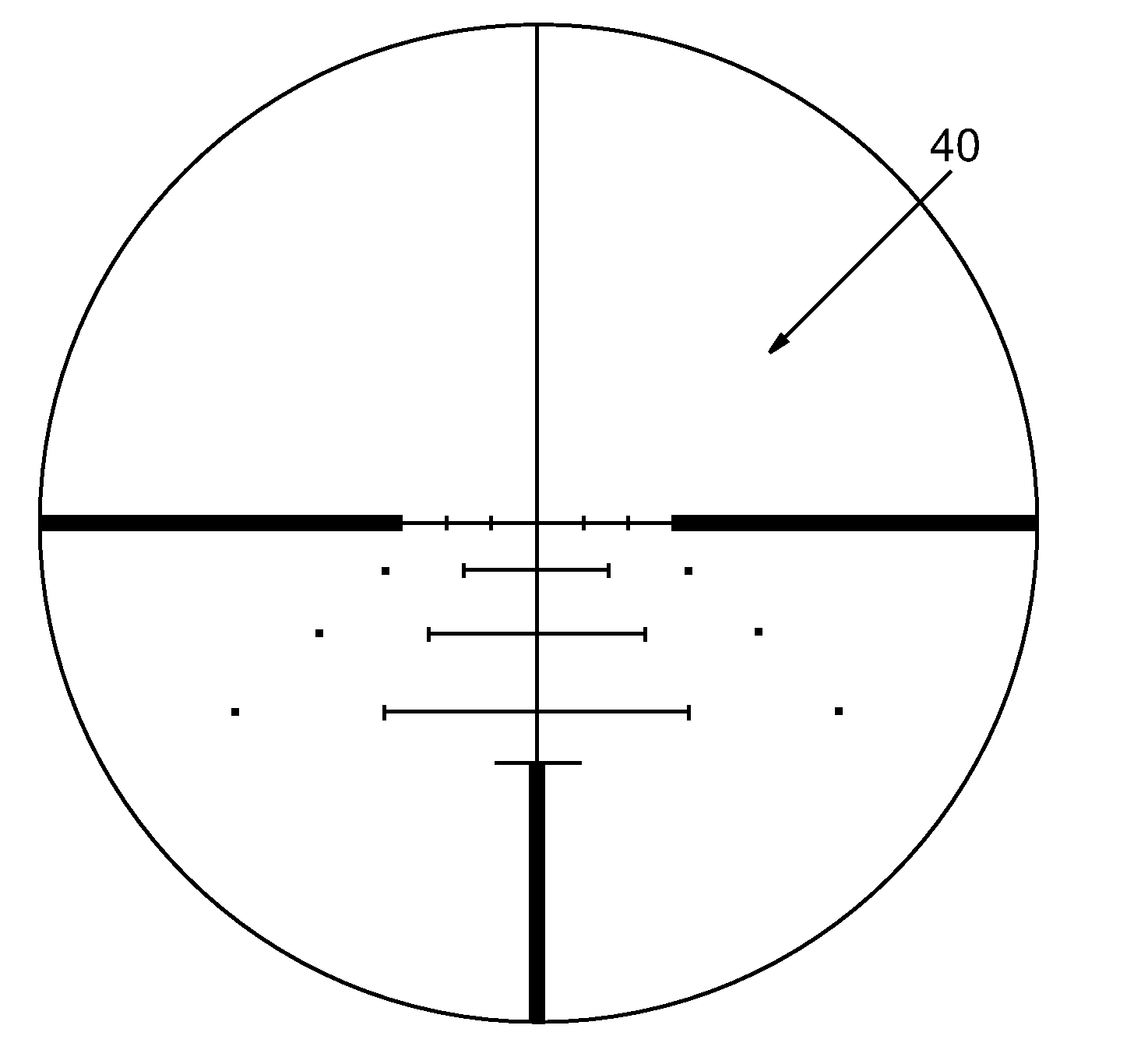
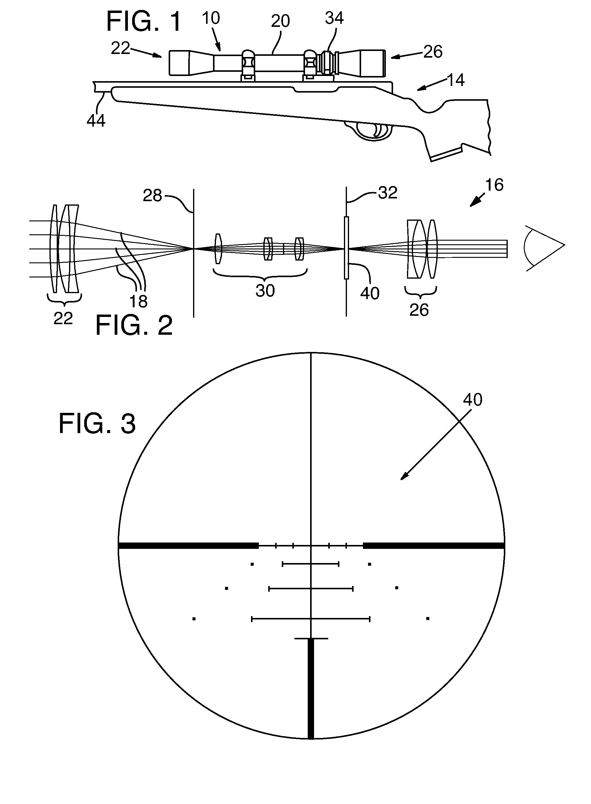
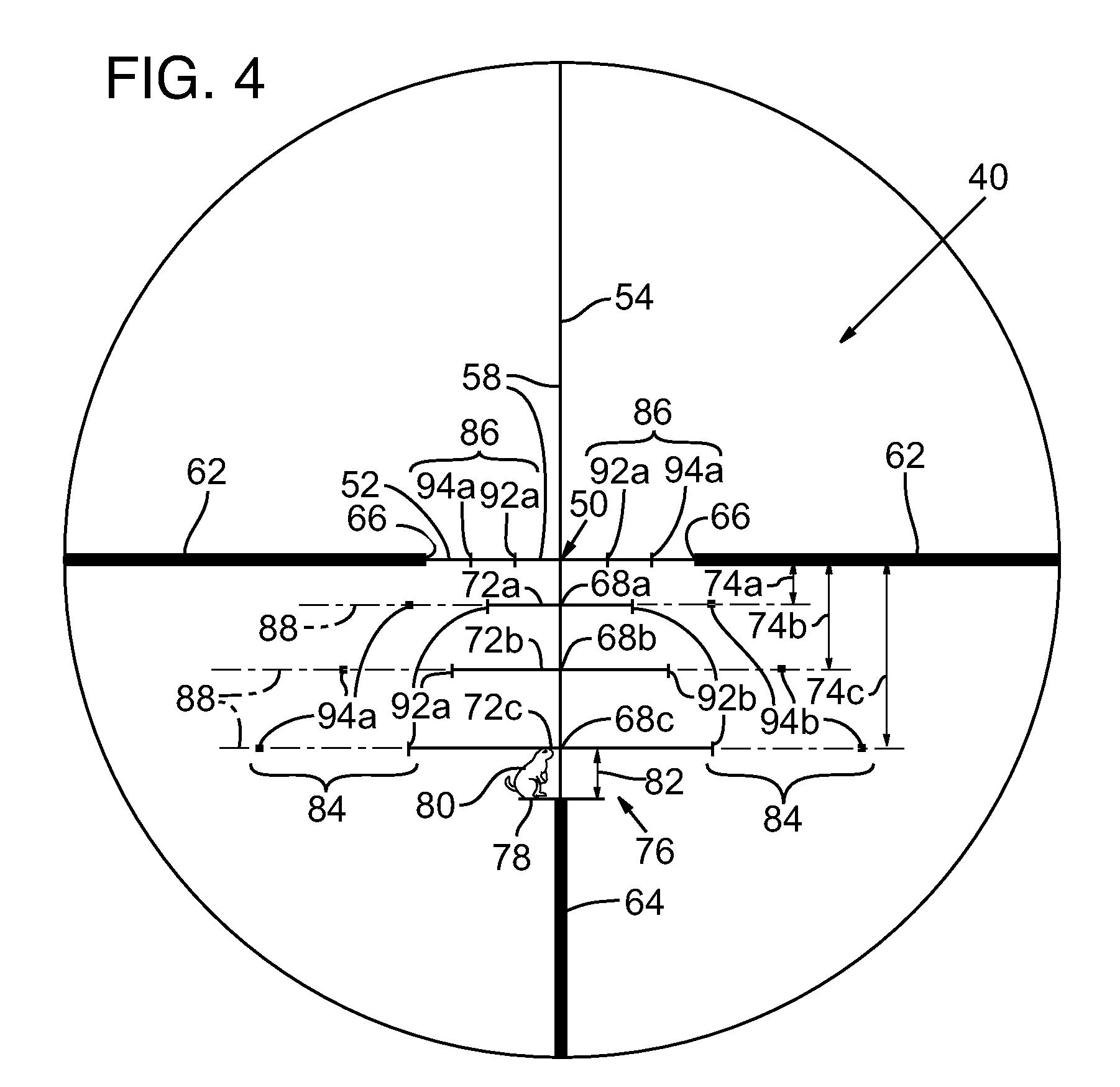
The patent describes a reticle for a projectile weapon aiming system that includes a primary aiming mark and two or more secondary aiming marks. The secondary aiming marks are positioned to compensate for ballistic drop at different ranges for a selected group of ammunition. The reticle can be adjusted to compensate for different ammunition and firing velocities by adjusting the optical power of the riflescope. The reticle also includes windage aiming marks to compensate for the effect of crosswinds on the trajectory of the projectile. The technical effect of this invention is to improve the accuracy and reliability of aiming in various shooting conditions.

Problems solved by technology

Adjustment of the elevation and windage is time consuming and may require the shooter to take his or her eyes off the target while manipulating the adjustment mechanisms.
However, Rubbert does not provide an aiming mark or points of reference when the target is at a range such that it does not fit any of the apertures.
The apparent spacing of the target-spanning and aiming apertures can be changed by varying the optical power of the riflescope; however, due to a limited amount of optical power adjustment available, the riflescope of Rubbert is useful only for aiming at targets within a limited size range.
Attempting to fit smaller or larger targets in the apertures would result in gross aiming errors.

Method used


Image

  • Ballistic reticle and riflescope for projectile weapon aiming system
  • Ballistic reticle and riflescope for projectile weapon aiming system
  • Ballistic reticle and riflescope for projectile weapon aiming system

Examples


Embodiment Construction

[0026]Throughout the specification, reference to “one embodiment,”“an embodiment,” or “some embodiments” means that a particular described feature, structure, or characteristic is included in at least one embodiment. Thus appearances of the phrases “in one embodiment,”“in an embodiment,” or “in some embodiments” in various places throughout this specification are not necessarily all referring to the same embodiment. Furthermore, the described features, structures, or characteristics may be combined in any suitable manner in one or more embodiments.

[0027]Furthermore, the described features, structures, characteristics, and methods may be combined in any suitable manner in one or more embodiments. Those skilled in the art will recognize that the various embodiments can be practiced without one or more of the specific details or with other methods, components, materials, etc. In other instances, well-known structures, materials, or operations are not shown or not described in detail to...


PUM


Abstract

A reticle of a projectile weapon aiming system such as a riflescope includes a primary aiming mark adapted to be sighted-in at a first selected range and further includes a plurality of secondary aiming marks spaced apart below the primary aiming mark. The secondary aiming marks are positioned to compensate for ballistic drop at preselected incremental ranges beyond the first selected range, for a selected group of ammunition having similar ballistic characteristics. Angles subtended by adjacent aiming marks of the reticle can be adjusted by changing the optical power of the riflescope, to thereby compensate for ballistic characteristics of different ammunition. In some embodiments, the reticle includes a set of windage aiming marks spaced apart along at least one secondary horizontal axis intersecting a selected one of the secondary aiming marks, to facilitate compensation for the effect of crosswinds on the trajectory of the projectile.

Description

RELATED APPLICATIONS[0001]This application is a divisional application of U.S. patent application Ser. No. 10 / 933,856, filed Sep. 3, 2004, which claims the benefit of U.S. Provisional Patent Application No. 60 / 518,377, filed Nov. 4, 2003, both of which are incorporated herein by reference. This application is also related to U.S. design Pat. Nos. D506,520, D517,153, and D536,762 all titled “RETICLE FOR A GUNSIGHT OR OTHER PROJECTILE WEAPON AIMING DEVICE” and filed Nov. 4, 2003.TECHNICAL FIELD[0002]This application relates to projectile weapon aiming systems such as riflescopes, to reticle configurations for projectile weapon aiming systems, and to associated methods of compensating for ballistic characteristics.BACKGROUND OF THE INVENTION[0003]Projectile weapon aiming systems are discussed herein principally with reference to their use on rifles and embodied in telescopic sights commonly known as riflescopes. It will become apparent, however, that projectile weapon aiming systems ma...

Claims


Application Information

Patent Timeline
Patent Type & Authority Applications(United States)
IPC IPC(8): F41G1/387G02B23/00F41G1/38
CPCF41G1/38
Inventor ZADEREY, SERGETIMM, STEVEN R.WILLIAMS, GARY R.PETERS, VICTORIA J.PETER, LAURALESSER, TIMO'CONNOR, TIM L.
Owner LEUPOLD & STEVENS
Learn More