Modular power actuator

Active Publication Date: 2009-08-13
GM GLOBAL TECH OPERATIONS LLC +1
View PDF15 Cites 24 Cited by
  • Summary
  • Abstract
  • Description
  • Claims
  • Application Information

AI Technical Summary

Benefits of technology

[0008]Accordingly, the subject invention provides a modular power actuator assembly, in which the position of the motor and the torque transmission device relative to the adjustment mechanism is changeable about the screw axis. This permits a

Problems solved by technology

This results in manufactures having to produce several differen

Method used


Image

  • Modular power actuator
  • Modular power actuator
  • Modular power actuator

Examples


Embodiment Construction

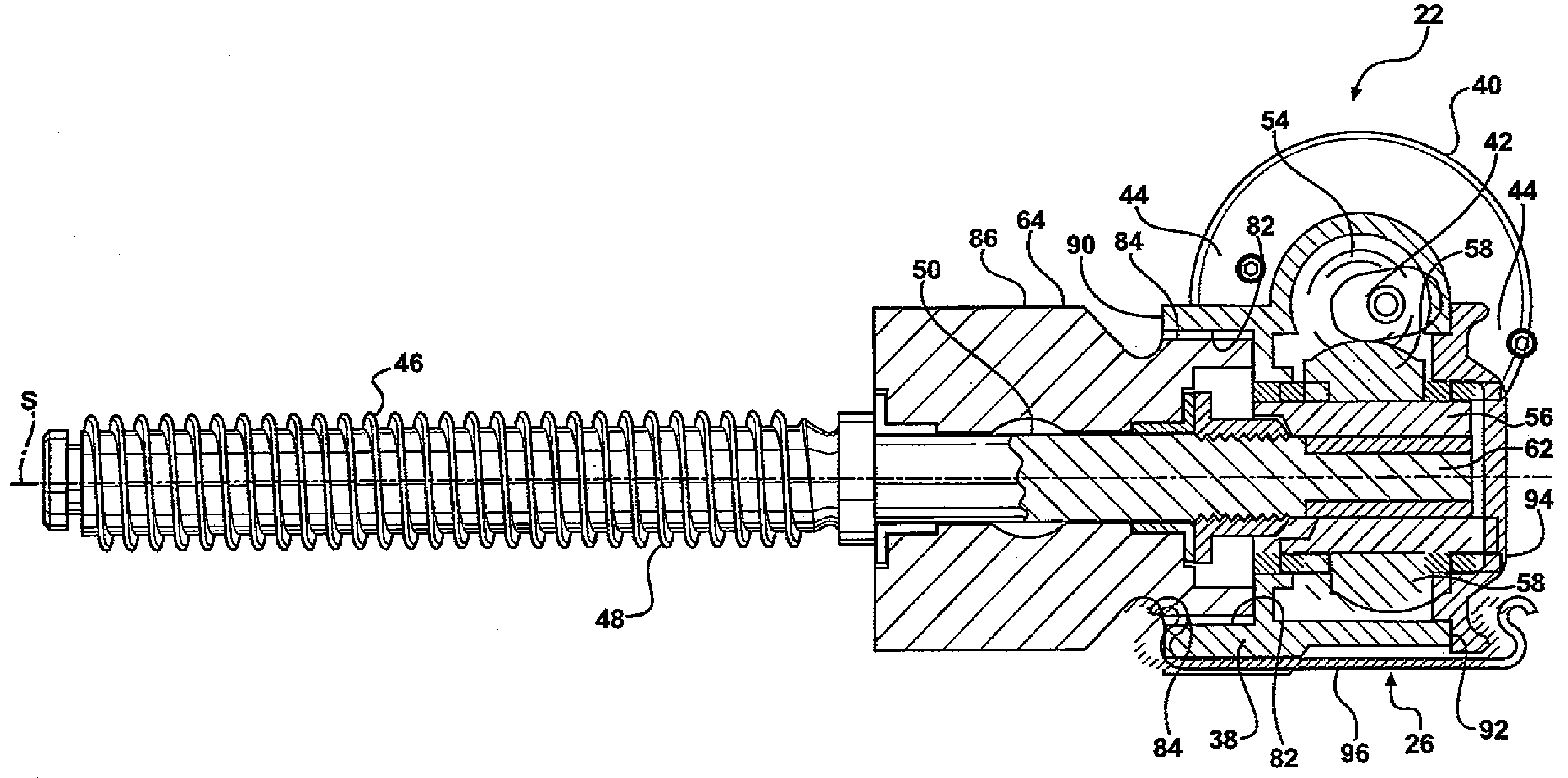
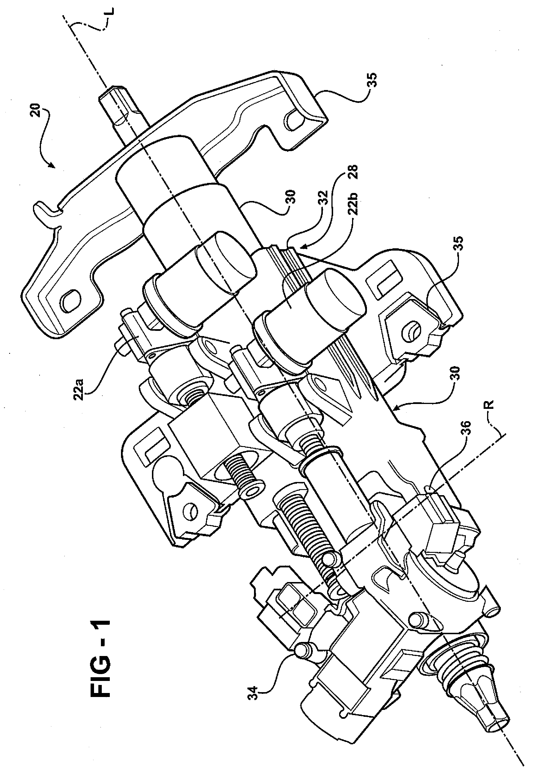
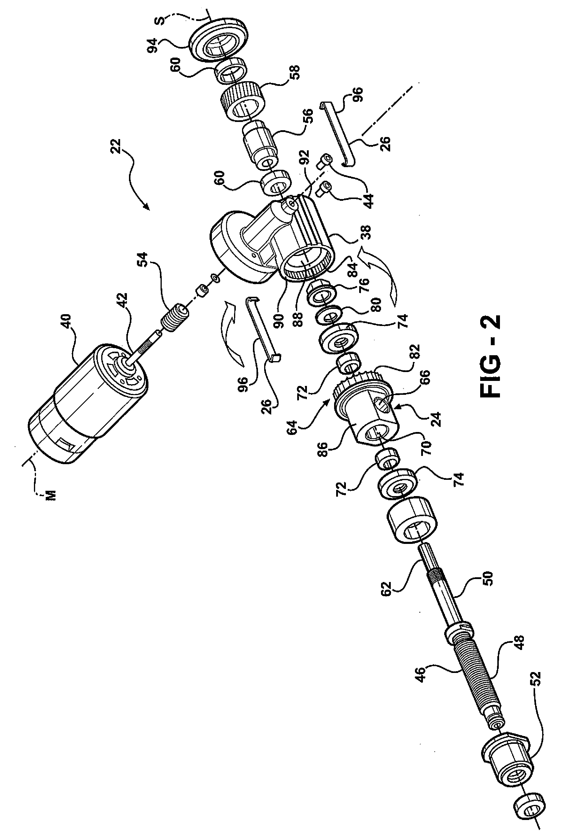
[0025]Referring to the Figures, wherein like numerals indicate corresponding parts throughout the several views, a steering column assembly is shown generally at 20. The steering column assembly 20 incorporates a power actuator assembly 22 therein. While shown in combination with the steering column assembly 20, it should be appreciated that the power actuator assembly 22 of the subject invention may be incorporated into different devices other than the steering column assembly 20 shown and described herein.

[0026]Referring to FIG. 1, the steering column assembly 20 is for a vehicle, and supports a steering wheel (not shown) for steering the vehicle. The steering column assembly 20 comprises a column jacket 28. The column jacket 28 includes a lower column jacket 30 and an upper column jacket 32. The upper column jacket 32 is longitudinal movable along a longitudinal axis L relative to the lower column jacket 30 to telescopically adjust the position of the steering wheel. A mounting b...


PUM


Abstract

A power actuator assembly includes a torque transmission device, a motor mounted to the torque transmission device extending along a motor axis, and a screw coupled to the torque transmission device and extending along a screw axis. An adjustment mechanism interconnects the screw and the torque transmission device and permits selective rotational adjustment between the adjustment mechanism and the torque transmission device to rotate the motor relative to the torque transmission device. A connecting device releasably interconnects the adjustment mechanism to the torque transmission device to permit repeated re-positioning of the motor relative to the torque transmission device.

Description

BACKGROUND OF THE INVENTION[0001]1. Field of the Invention[0002]The subject invention relates to a power actuator assembly, and more specifically to an adjustable steering column assembly having a power actuator for moving the adjustable steering column assembly.[0003]2. Description of the Prior Art[0004]Power actuator assemblies of the type described herein are utilized in several different devices, including an adjustable steering column in a vehicle. The adjustable steering columns may adjust in both a rake (tilt) direction and in a telescoping direction. These adjustable steering columns commonly utilize the power actuator assembly to move the steering column in the rake direction and / or the telescope direction.[0005]Typically, the power actuator assembly comprises a torque transmission device. A motor is mounted to the torque transmission device and extends along a motor axis. The motor includes an output shaft that is rotatable about the motor axis. A screw is rotatably suppor...

Claims


Application Information

Patent Timeline
IPC IPC(8): B62D1/18F16H1/18
CPCB62D1/181F16H1/16F16H25/20Y10T74/19823H02K7/06Y10T74/19828F16H2025/209
Inventor MENJAK, RATKOMAGNUS, BRIAN J.THOMAS, STEVEN M.BARRETT, THOMAS A.ISLAM, MOHAMMAD S.BOSWELL, KAREN A.SINIFF, DAVID K.TOMASINO, MICHAEL A.ROULEAU, JAMES E.SCHULTZ, STEVEN J.
Owner GM GLOBAL TECH OPERATIONS LLC
Why Eureka
Try Eureka