Defect Detection Apparatus, Defect Detection Method and Computer Program

a technology of defect detection and defect detection method, applied in the field of defect detection apparatus, a defect detection method and a computer program, can solve the problems of low accuracy in the determination of defects in regard to objects such as objects with subtly changing shapes, width, size, and the like, and the inability to accurately specify the defect shape of an obj

Active Publication Date: 2009-08-13
KEYENCE
View PDF2 Cites 25 Cited by
  • Summary
  • Abstract
  • Description
  • Claims
  • Application Information

AI Technical Summary

Benefits of technology

[0033]According to the present invention, since a teaching image is not required to be prepared in advance nor is the outline required to have a specific shape such as a straight line or a circular, a defect can be detected in arbitrary shape. Further, calculating the repre...

Problems solved by technology

However, there has been a problem in the image processing method disclosed in Japanese Patent Application Laid-Open No. 2001-175865 in that accurate positioning of the teaching image and the picked-up image is required, causing lower accuracy in defect determination in regard to an object such as one with its shape subtly changing.
Further, there has been a problem in the inspection method disclosed in Japanese Patent Application Laid-Open No. 2000-055827 in that, even when the presence of the defect is detected, the width, size, and the like of the defect cannot be accurately specified due to the use of differential information in the determination.
Further, there...

Method used


Image

  • Defect Detection Apparatus, Defect Detection Method and Computer Program
  • Defect Detection Apparatus, Defect Detection Method and Computer Program
  • Defect Detection Apparatus, Defect Detection Method and Computer Program

Examples


first embodiment

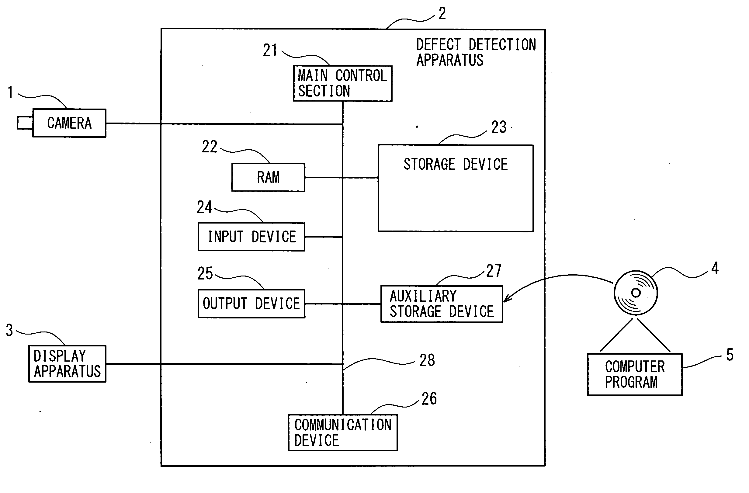
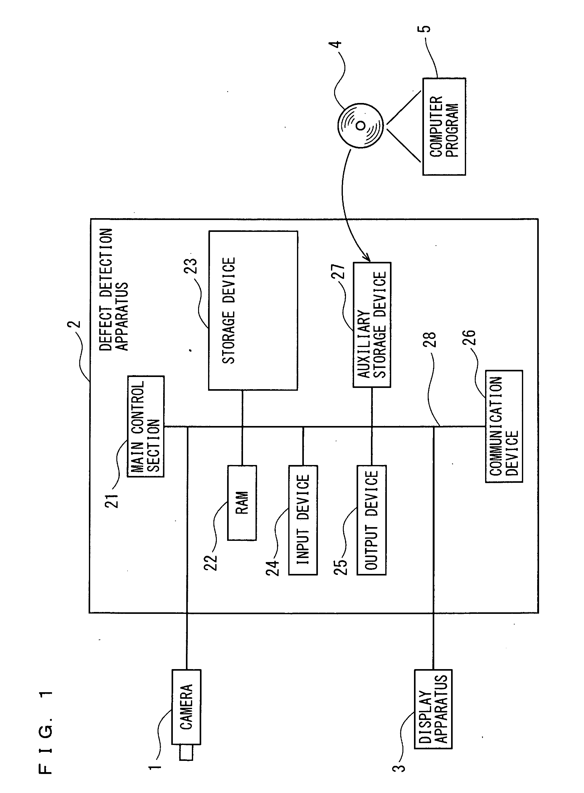
[0048]FIG. 1 is a block diagram schematically showing a configuration of a defect detection apparatus according to a first embodiment of the present invention. As shown in FIG. 1, a defect detection apparatus 2 according to the present first embodiment is connected with a camera 1 as an image pickup device for picking up a multi-valued image, and a display apparatus 3 which displays a picked-up multi-valued image or a generated image.

[0049]The defect detection apparatus 2 is configured of at least a CPU (Central Processing Unit), the main control section 21 made up of an LSI or the like, an RAM 22, a storage device 23, an input device 24, an output device 25, a communication device 26, an auxiliary storage device 27, and an internal bus 28 for connecting the foregoing hardware. The main control section 21 is connected to each of hardware sections of the defect detection apparatus 2 as described above through the internal bus 28, and controls the operation of each of the foregoing ha...

second embodiment

[0083]A configuration of a defect detection apparatus 2 according to a second embodiment of the present invention is similar to the first embodiment, and hence the same numerals are provided thereto and the detailed descriptions thereof are not given. The present second embodiment is different from the first embodiment in that weighting is performed on respective edge points based upon residuals, to calculate a representative-edge-point sequence based upon the weighting.

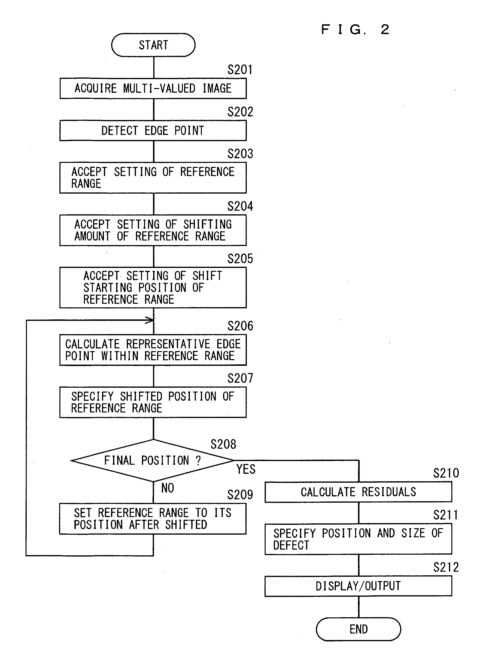
[0084]FIG. 9 is a flowchart showing a processing procedure of the main control section 21 of the defect detection apparatus 2 according to the second embodiment of the present invention. In FIG. 9, since processing to step S210 are the same processing as those in FIG. 2 of the first embodiment, the detailed description thereof are not given. The main control section 21 of the defect detection apparatus 2 according to the second embodiment of the present invention calculates, with respect to respective edge points, re...


PUM


Abstract

There are provided a defect detection apparatus, a defect detection method, and a computer program, which are capable of setting an appropriate reference line with respect to a plurality of edge points, to accurately detect a defect based upon a difference of each edge point, and in which a plurality of edge points are detected from an image including an edge of the object, a representative edge point representing the edge points present within a reference range having a prescribed width is calculated in each shifted position of the reference range while the reference range is sequentially shifted, residuals between a plurality of calculated representative edge points and corresponding edge points are calculated, a position and a size of the defect are specified based upon the calculated residuals, and the residuals are weighted and a representative edge point is repeatedly calculated, to obtain an apparent approximate curve (representative-edge-point sequence).

Description

CROSS-REFERENCE TO RELATED APPLICATIONS[0001]The present application claims foreign priority based on Japanese Patent Application No. 2008-027143, filed Feb. 7, 2008, the contents of which is incorporated herein by reference.BACKGROUND OF THE INVENTION[0002]1. Field of the Invention[0003]The present invention relates to a defect detection apparatus, a defect detection method and a computer program, which are capable of setting a reference line with respect to a plurality of edge points having connectivity, to accurately detect a defect such as a burr or a crack based upon a difference of each edge point from the reference line.[0004]2. Description of the Related Art[0005]Conventionally, in a case of detecting the presence of a defect such as a burr or a crack from an picked-up image, for example as for an object having an edge in curved shape, a plurality of edge points are acquired at fixed intervals or fixed angles along the edge, to calculate a free curve enveloping an acquired e...

Claims


Application Information

Patent Timeline
IPC IPC(8): G06K9/00
CPCG06K9/6204G06T7/0085G06T7/0083G06T7/0004G06T7/12G06T7/13G06V10/752
Inventor SHIMODAIRA, MASATO
Owner KEYENCE
Why Eureka
Try Eureka