
Automatic analyzer

a technology of automatic analyzer and analyzer, which is applied in the field of automatic analyzer, can solve the problems of not being able to identify the results on quality, not being able to follow or estimate the operation of the automatic analyzer based on visual inspection, and not being able to identify the results , to achieve the effect of quick action and efficient assurance of the reliability of the analysis results

Active Publication Date: 2009-08-13
HITACHI HIGH-TECH CORP
View PDF24 Cites 13 Cited by
  • Summary
  • Abstract
  • Description
  • Claims
  • Application Information

AI Technical Summary

Benefits of technology

The present invention provides an automatic analyzer that can easily acquire and provide detailed information about the analysis and inspection performed on a sample. This information can be used to evaluate the validity and accuracy of the result of analysis and inspection, and to identify the cause of any abnormal state that may occur. The analyzer can also automatically perform reinspection to ensure the reliability of the result of analysis. The technical effects of the invention include improved accuracy and reliability of analysis results, as well as efficient and effective investigation and resolution of abnormal states.

Problems solved by technology

Therefore, it is impossible to follow or estimate the operation of the automatic analyzer based on visual inspection.
However, because there are a variety of methods for leaving the result of calibration, detailed information about the analysis and inspection, which have been performed to derive the calibration curve, is not necessarily left.
Moreover, it is not possible to identify the result on quality control for ensuring the accuracy of the analysis and inspection that have been performed to derive the calibration curve.
If the user is warned of an abnormal state of the automatic analyzer, it is difficult for the user to keep the current situation of the automatic analyzer unchanged until the serviceman arrives.
The operation condition of the automatic analyzer, which is explained by the user, also lacks in sufficiency and correctness.
Thus, it takes much time until appropriate measures are taken.

Method used


Image

  • Automatic analyzer
  • Automatic analyzer
  • Automatic analyzer

Examples


Embodiment Construction

[0035]An embodiment of the present invention will be described below with reference to the accompanying drawings.

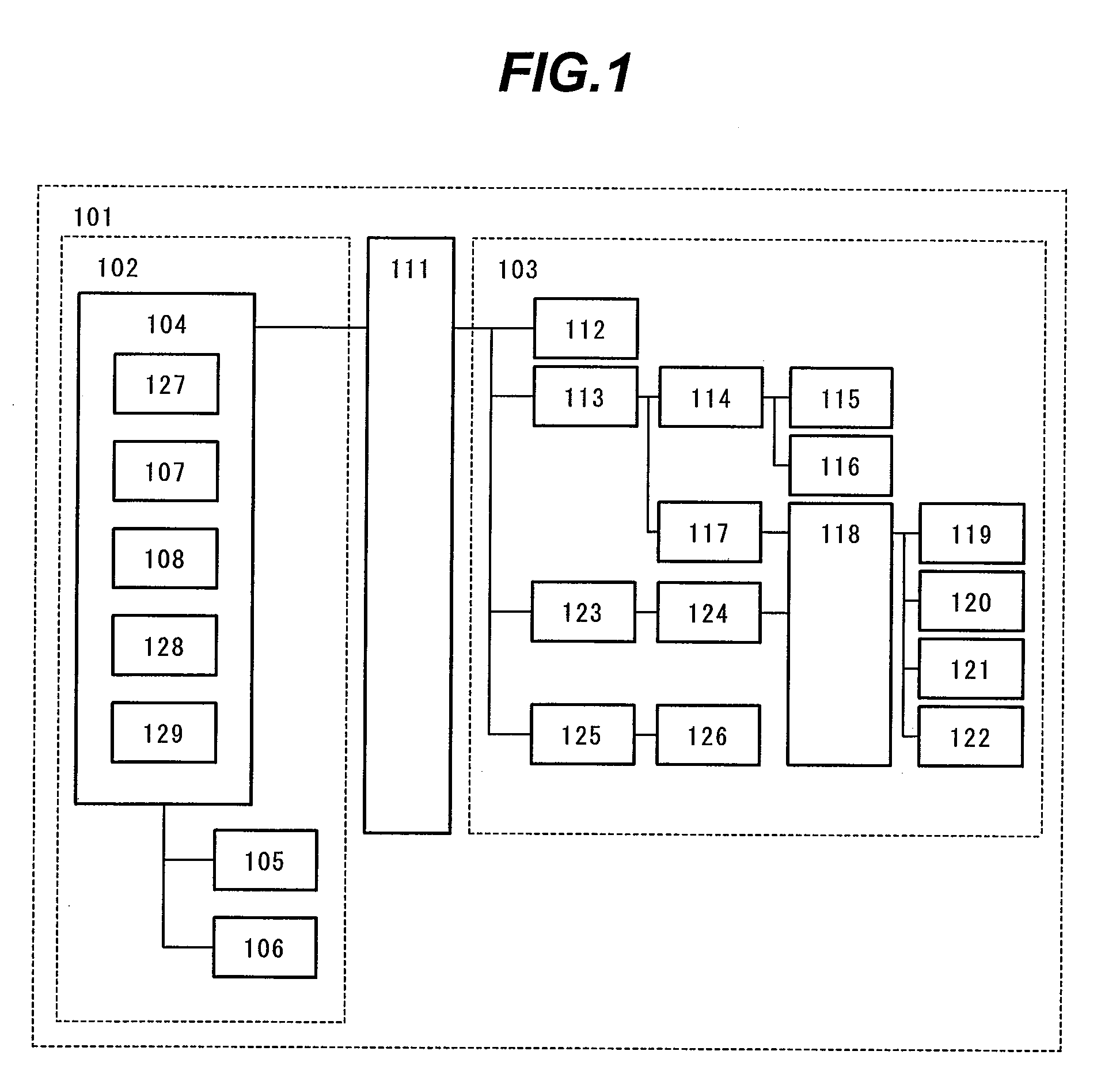
[0036]The configuration of an automatic analyzer according to the present invention will be schematically described with reference to FIGS. 1 and 11.

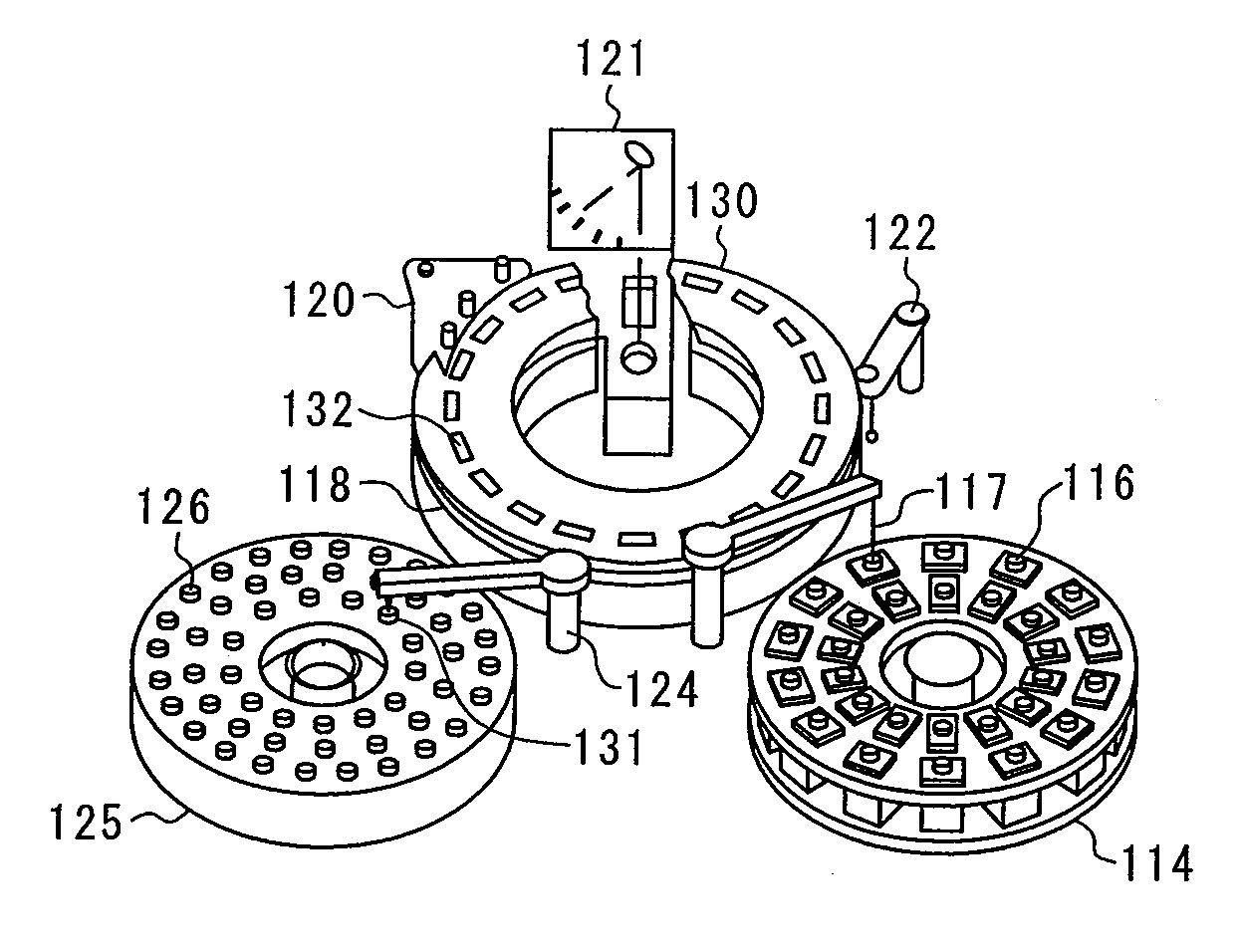
[0037]FIG. 11 is a schematic diagram of an automatic analyzer according to the present invention. In FIG. 11, a reference numeral 125 represents a sample disk, a reference numeral 114 representing a reagent disk, a reference numeral 130 representing a reaction disk, a reference numeral 118 representing a reaction vessel, a reference numeral 124 representing sample pipetting mechanism, a reference numeral 122 representing a mixer, a reference numeral 121 representing a multiwavelength photometer. A reference numeral 120 represents a rinsing mechanism, a reference numeral 126 representing a sample container, a reference numeral 116 representing reagent cassette, a reference numeral 132 representing a reaction container, a refer...


PUM

PropertyMeasurementUnit
concentrationaaaaaaaaaa
speedaaaaaaaaaa
timeaaaaaaaaaa

Abstract

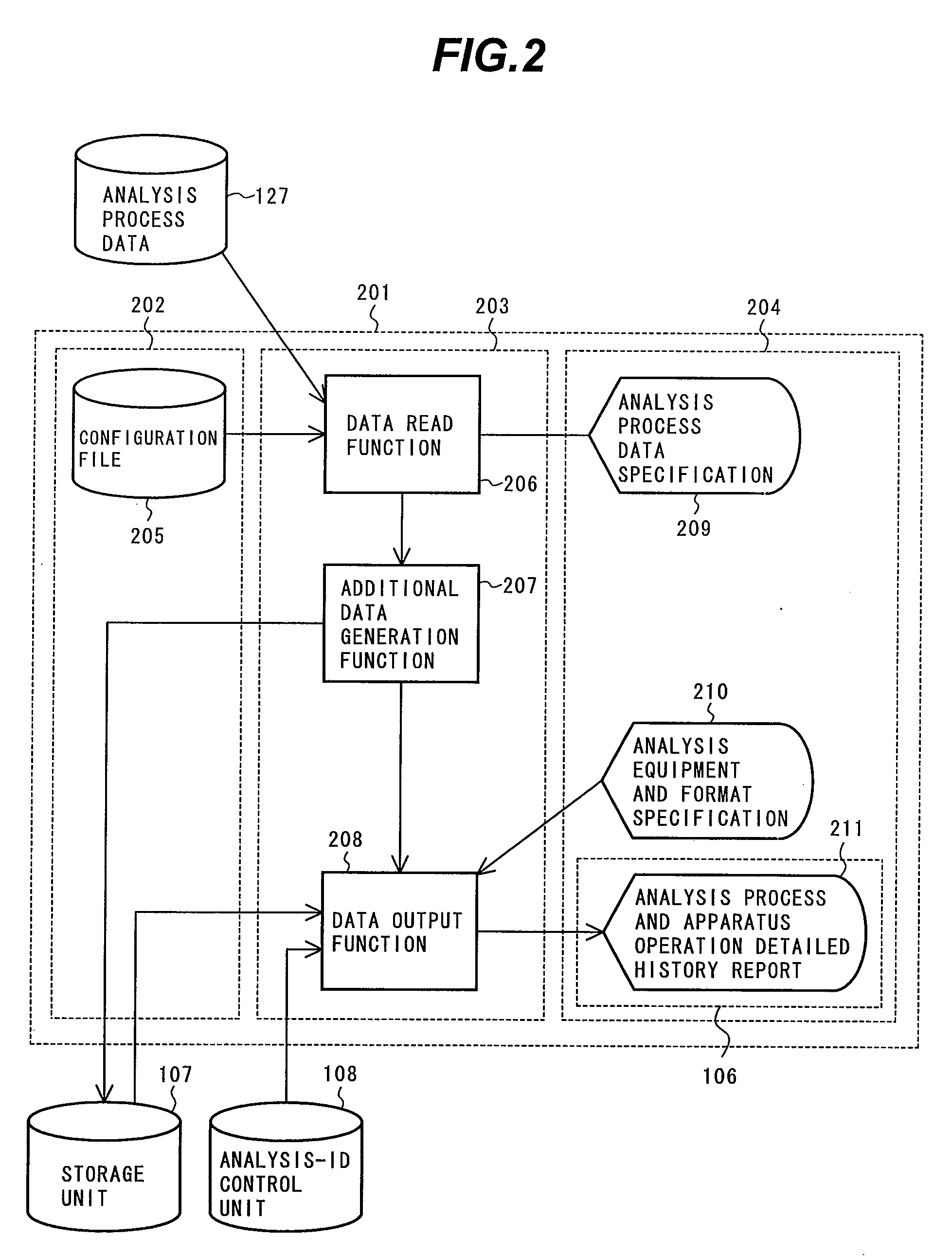
An automatic analyzer includes a storage unit for storing operation information, information about usage histories of expendable supplies provided for the analysis, and an analysis-ID control unit giving an ID to the analysis, the analysis ID being used as information for identifying the analysis to derive a calibration curve. Data stored in the storage unit is organized along the same time axis both in the order of samples subjected to the analysis and inspection, and in the order of analysis items, so that the data is output in a total data display area. The data is organized from the viewpoint of an analysis process of an analysis item of each sample. By use of information used to identify an influence range based on a kind of an abnormal state, which is stored beforehand, a judgment is made as to whether or not it is necessary to perform reinspection.

Description

BACKGROUND OF THE INVENTION[0001]1. Field of the Invention[0002]The present invention relates to an automatic analyzer for performing biochemical analysis and immunological analysis for blood and the like. The invention more particularly relates to an automatic analyzer which has means for recording information about the operation of analysis equipment constituting an automatic analyzer, information about a situation in which expendable supplies including a reagent are being used, and information about the relation with various kinds of management data and calculation data used in an analysis process, wherein the data (information) stored in the means is displayed in such a way as to be capable of showing the correctness of an analysis process and capable of investigating a cause of an abnormal state. Moreover, the present invention concerns a function of automatically judging whether or not it is necessary to perform reinspection, and of automatically executing the reinspection whe...

Claims


Application Information

Patent Timeline
Patent Type & Authority Applications(United States)
IPC IPC(8): G01N35/00
CPCG01N35/00603G01N2035/00821G01N35/00732G01N35/00693G16H10/40G01N2035/00891
Inventor IIZUMI, NORIKOTOMIYAMA, TOMOKOTAKAGI, YOSHIMITSUIMAI, KYOKOKODAMA, RYUICHIROMIMURA, TOMONORI
Owner HITACHI HIGH-TECH CORP
Learn More