
Intraocular lens inserting instrument

Active Publication Date: 2009-08-13
HOYA CORP
View PDF100 Cites 70 Cited by
  • Summary
  • Abstract
  • Description
  • Claims
  • Application Information

AI Technical Summary

Benefits of technology

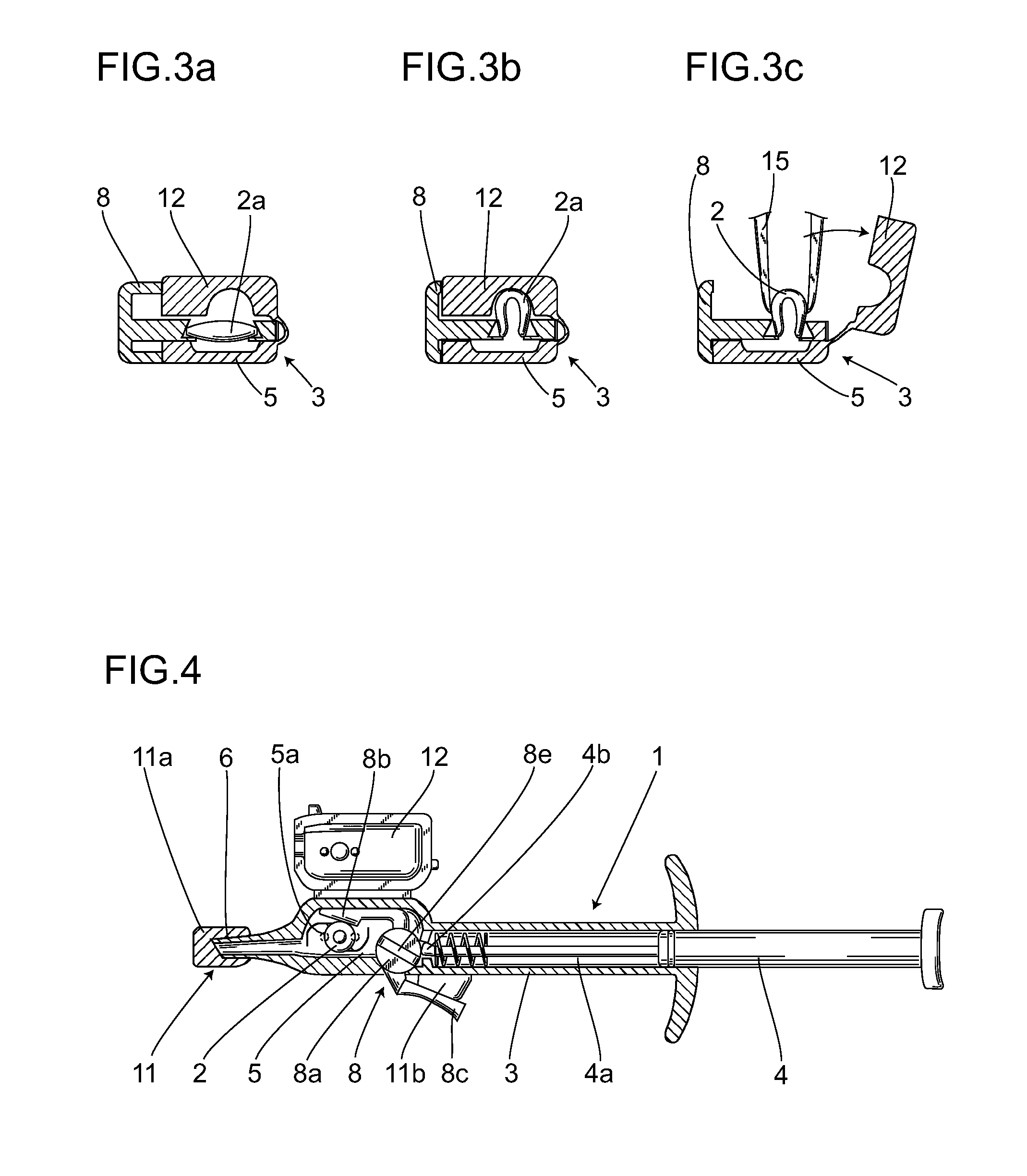
[0018]The intraocular lens inserting instrument according to the first aspect enables an intraocular lens to be implanted in an eye using an injector with the intraocular lens set in advance, while also allowing the folded intraocular lens to be grasped by tweezers and implanted in an eye when necessary after the intraocular lens has been folded.
[0019]The intraocular lens inserting instrument according to the second aspect enables an intraocular lens to be folded in two, thus allowing the intraocular lens to be easily grasped by tweezers.
[0024]The intraocular lens inserting instrument according to the seventh aspect provides a locking mechanism in the folding members that prevents the intraocular lens from being folded unless the locking mechanism is unlocked, thus preventing unintentional deformation of the intraocular lens.

Problems solved by technology

However, a preset injector disclosed in the above patent documents must move the lens from the stationary position to a usable position during its use, and the risk of problems accompanying the movement operation cannot be eliminated.
Further, because the injector has a mechanism that moves the lens to a usable position and begins pushing with the optical area being nearly undistorted, the discharge device is required to have a long movement distance.
This increases the possibility of a problem occurring during operation and creates structural limitations, such as making the overall length of the injector longer.
In this state, if the intraocular lens is pressed against the fine areas of the lens placing section and narrow tube member, a very high load is placed on the lens, which could damage the lens.
In addition, the lens is completely enclosed in the tube member, so it is not possible to remove, after deformation, a lens that has been deformed inside the inserting instrument.
Using such a multiple step operation, however, increases the risk of contaminating the eye with foreign matter or microbes and the possibility of dropping or damaging the lens through handling mistakes.
In the case of a preset injector in particular, the injector is shipped with the lens set inside, and none of the currently commercially available preset injectors were designed with the intention of using tweezers to remove the lens and, therefore, are not provided with a mechanism for safely removing the intraocular lens without breaking the injector.

Method used


Image

  • Intraocular lens inserting instrument
  • Intraocular lens inserting instrument
  • Intraocular lens inserting instrument

Examples


first embodiment

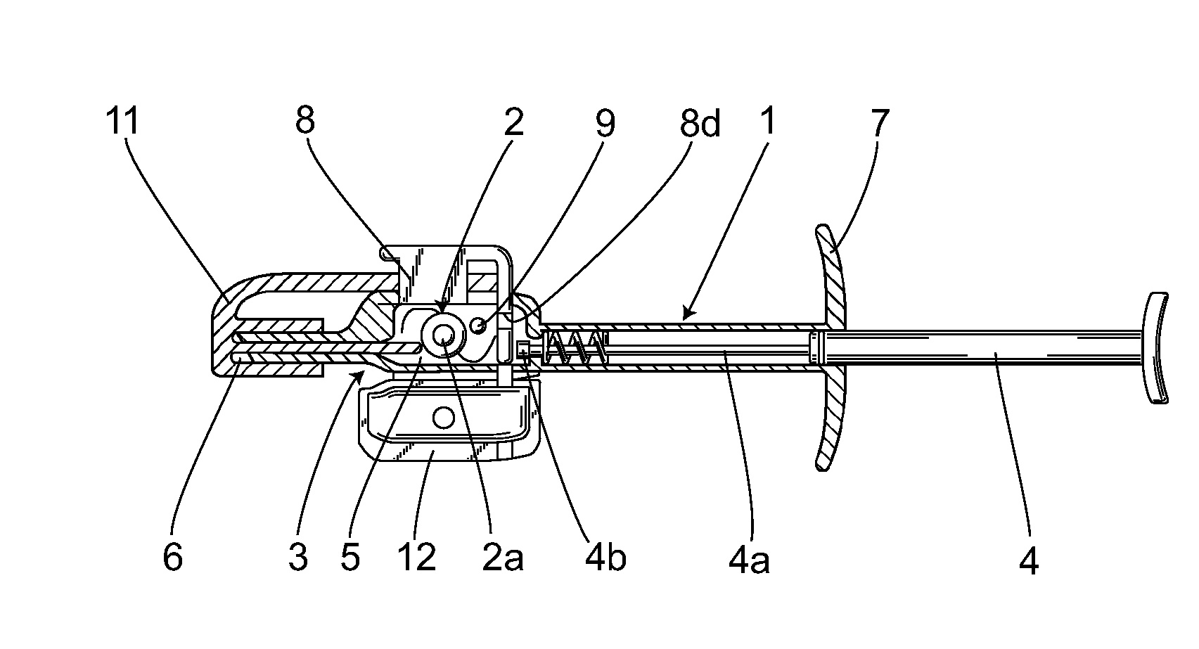
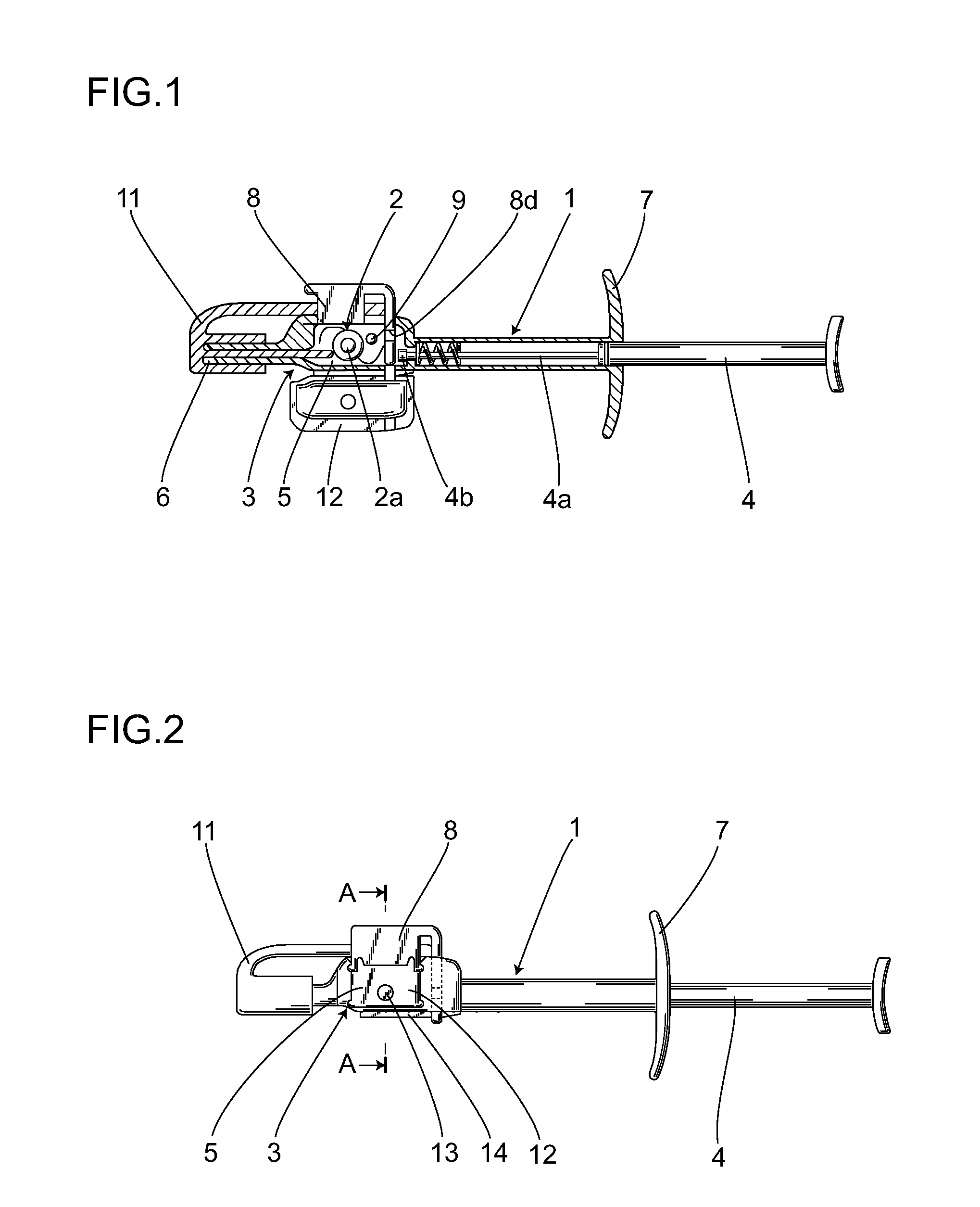
[0053]The present invention is described with reference to the drawings. FIG. 1 to FIG. 3 are diagrams showing an intraocular lens inserting instrument according to a the present invention. FIG. 1 provides a cross-section view showing the open / close lid in an open position and nozzle cap attached. The intraocular lens inserting instrument 1 is an intraocular lens inserting instrument 1 for inserting a foldable, flexible intraocular lens 2 in an eye and comprises a tubular body 3 through which the afore-mentioned intraocular lens 2 is passed and guided into the eye, a plunger 4 for discharging the compressed afore-mentioned intraocular lens 2 into an eye, folding members 8 for folding into two the intraocular lens 2 in a lens placing section 5 provided in the afore-mentioned body 3, and a means for removing the intraocular lens 2 from the afore-mentioned lens placing section 5.

[0054]The tubular body 3 is also called the hand piece, and a lens placing section 5 is provided in the mids...

third embodiment

[0075]This embodiment provides two folding members 8 in the lens placing section 5 where the afore-mentioned two folding members 8 are joined by a plate spring 17 and protrusions 8f are provided in the afore-mentioned two folding members 8 that lock at appropriate locations in the body 3 to counter the bias force of the afore-mentioned plate spring 17 to maintain the position of the afore-mentioned folding members 8. However, the joining method using the plate spring 17 differs from that of the The two folding members 8 are positioned in a V-shape with one edge connected to the plate spring 17. Further, the two folding members 8 are made to only rotate at a specific angle about the center of the plate spring 17. In other words, when the two folding members 8 are opened outwards, the two folding members 8 are positioned in a V-shape in the lens placing section 5 to obtain space for placing the optical area 2a of the lens. Therefore, this state allows for the lens 2 to be positioned ...


PUM


Abstract

An intraocular lens inserting instrument capable of folding a lens and pressing it by a plunger to discharge it into an eye and alternatively capable of taking out the folded lens by tweezers. The intraocular lens inserting instrument for inserting a foldable intraocular lens into an eye has a tubular body for allowing the intraocular lens to pass through it and introducing it into the eye, and a plunger for pressing the intraocular lens to discharge it into the eye, wherein the intraocular lens is folded by a folding member provided at a lens placing section. The lens placing section has an open / close lid so that the folded intraocular lens is accessible to be held by the tweezers.

Description

CROSS-REFERENCE TO RELATED APPLICATIONS[0001]This application is the national phase under 35 U.S.C. §371 of PCT International Application No. PCT / JP2006 / 300291, which has an International filing date of Jan. 12, 2006, designated in the United States and claims priority from Japanese Patent Application No. 2005-049700, filed Feb. 24, 2005. International Patent Application No. PCT / JP2006 / 300291 and Japanese Patent Application No. 2005-049700 are incorporated by reference herein in their entireties.FIELD OF THE INVENTION[0002]The present invention relates to an intraocular lens inserting instrument that inserts an intraocular lens into an eye in place of a lens removed by a cataract operation, and more particularly to an intraocular lens inserting instrument capable of grasping a folded intraocular lens by tweezers and inserting said intraocular lens into an eye.DESCRIPTION OF THE RELATED ART[0003]In cataract operations, the method of removing an opacified lens by phacoemulsification a...

Claims


Application Information

Patent Timeline
IPC IPC(8): A61F9/007
CPCA61F2/1662A61F2/1691A61F2/167
Inventor ICHINOHE, TAKASHIKUDOH, KAZUNORI
Owner HOYA CORP
Learn More