
Power tools

a technology for power tools and rip guides, which is applied in the field of power tools, can solve the problems of non-standard attachment interfaces of portable tool spindles, preventing the attachment of standard cutting elements, etc., and achieves the effects of improving the durability of the rip guide, and quick and easy removal of perforated materials

Inactive Publication Date: 2009-08-20
BLACK & DECKER INC
View PDF34 Cites 18 Cited by
  • Summary
  • Abstract
  • Description
  • Claims
  • Application Information

AI Technical Summary

Benefits of technology

[0003]One aspect of the present invention includes an accessory that provides the user with functionality to quickly and easily remove perforated material from the power tool cutting element. Certain portable tool spindles have non-standard attachment interfaces preventing the attachments of standard cutting elements. To accommodate non-standard attachment interfaces, certain cutting elements have perforations that will change the standard attachment on the cutting element to one that will match the non-standard spindle. The present disclosure includes a perforated material remover that provides the user with functionality to quickly and easily remove perforated material from the power tool cutting element allowing the cutting element to be attached to the power tool.
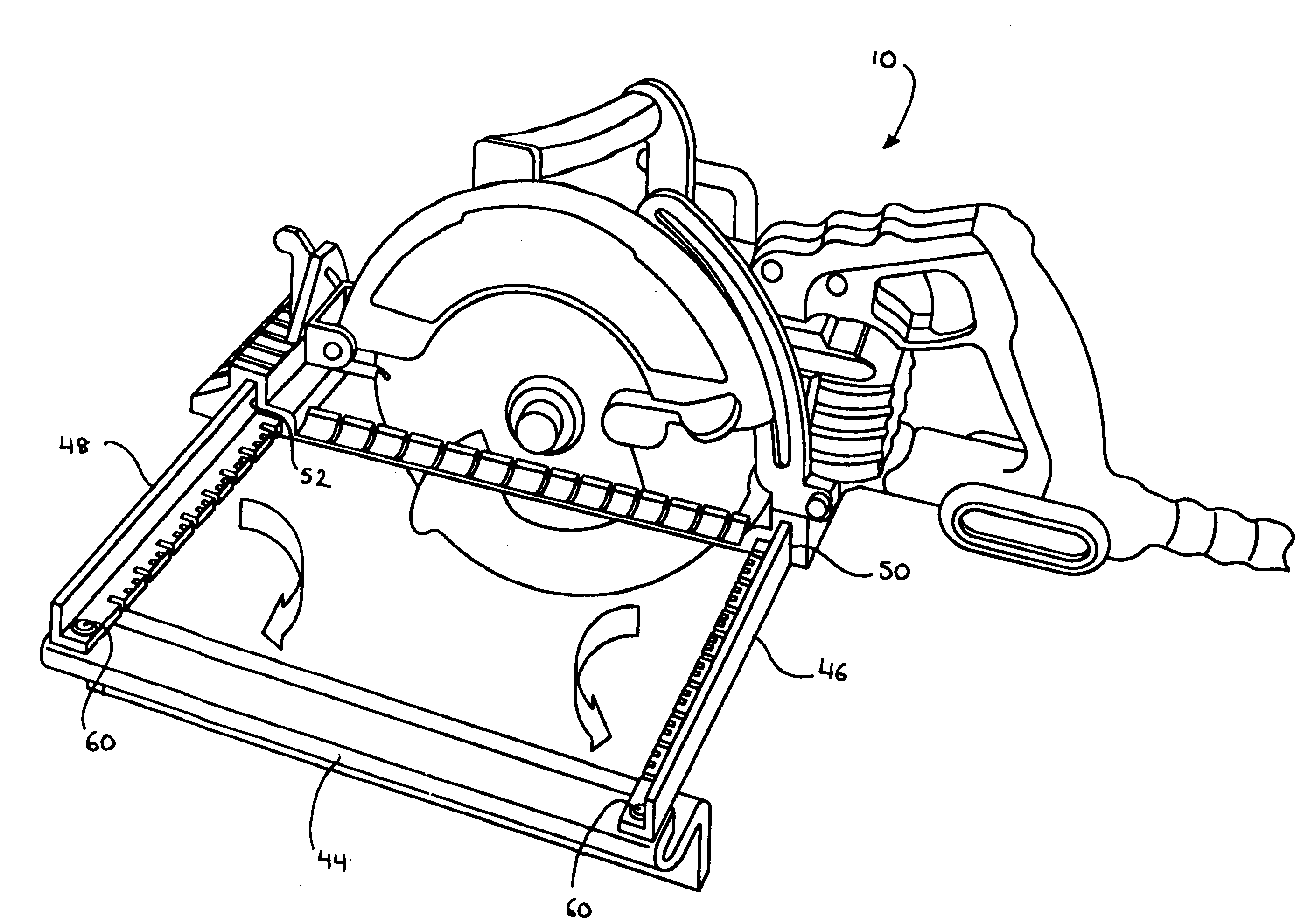
[0004]According to another aspect of the present invention, rip guides are used as an accessory with portable saws to assist the user in making accurate rip cuts on a work piece. The present disclosure includes a rip guide having a long guide edge and two attachment points to the shoe / base of the saw. The rip guide accessory is attached to the base / shoe via a pair of L-shaped openings. The L-shaped openings are versatile in that they are compatible with existing rip guides and they accept the L-shaped support arms of the rip guide of the present disclosure. The L-shaped geometry provides a significant improvement in durability of the rip guide. The support arms can be fixed to the guide edge using a pivot connection, such as by bolts, to be folded to a more compact size for storage. Another alternate design allows the rip guide to be folded along its support arms and allows the support arms to slide with respect to the guide edge as well as each other to minimize the rip guide's dimensions when folded for storage.
[0005]According to yet another aspect of the present disclosure, power saws typically have the ability bevel to allow an angled cut into the workpiece. The present disclosure includes two bevel scales located on the castings associated with the saw shoe to provide the user with an accurate measurement scale to quickly and easily set the angle of cut. Preferably, the two bevel scales complement each other with one scale having a coarse measurement scale and the other bevel scale having a fine measurement scale.

Problems solved by technology

Certain portable tool spindles have non-standard attachment interfaces preventing the attachments of standard cutting elements.

Method used


Image

  • Power tools
  • Power tools
  • Power tools

Examples


Embodiment Construction

[0019]The following description is merely exemplary in nature and is not intended to limit the present disclosure, application, or uses. It should be understood that throughout the drawings, corresponding reference numerals indicate like or corresponding parts and features.

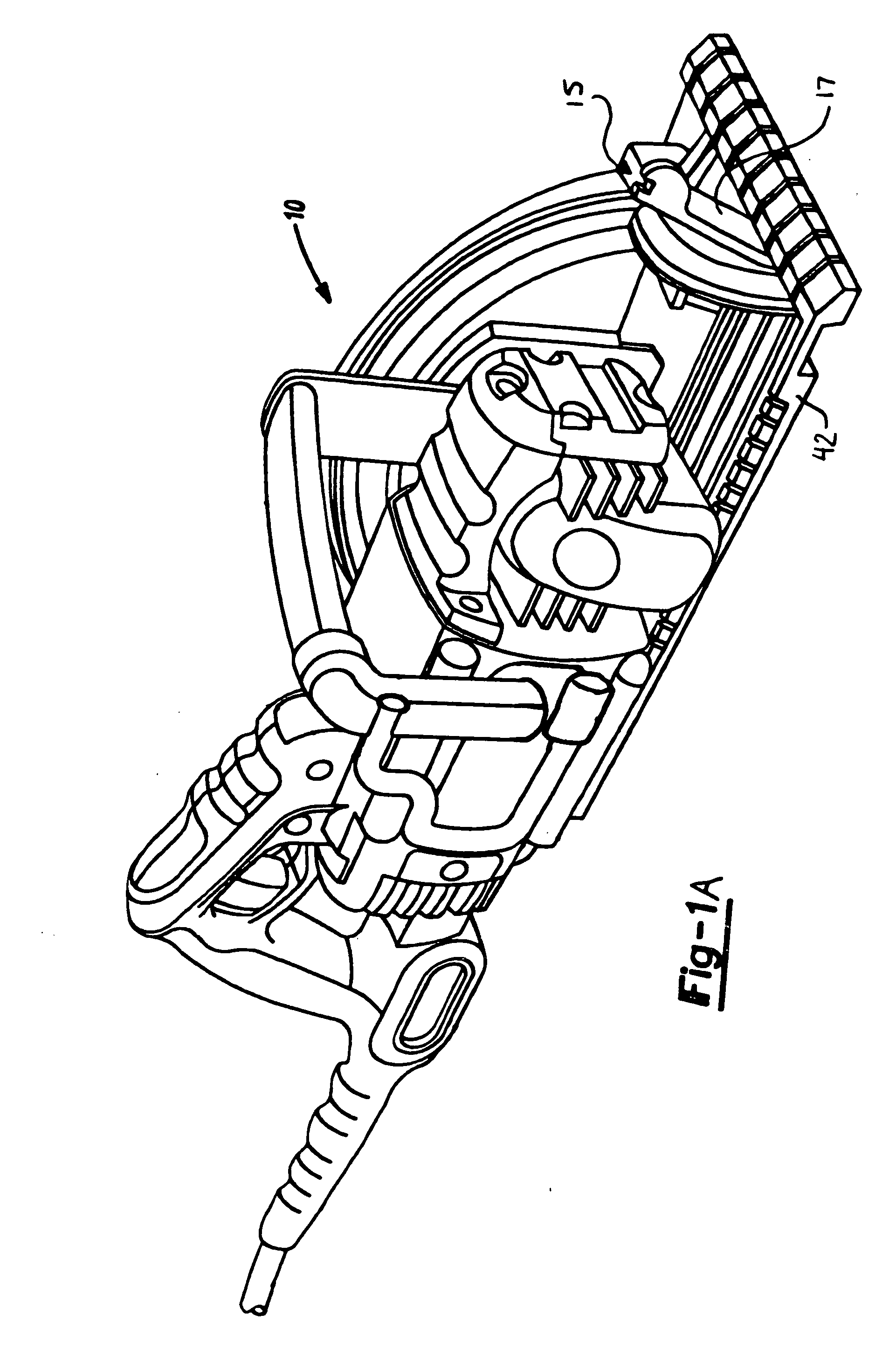
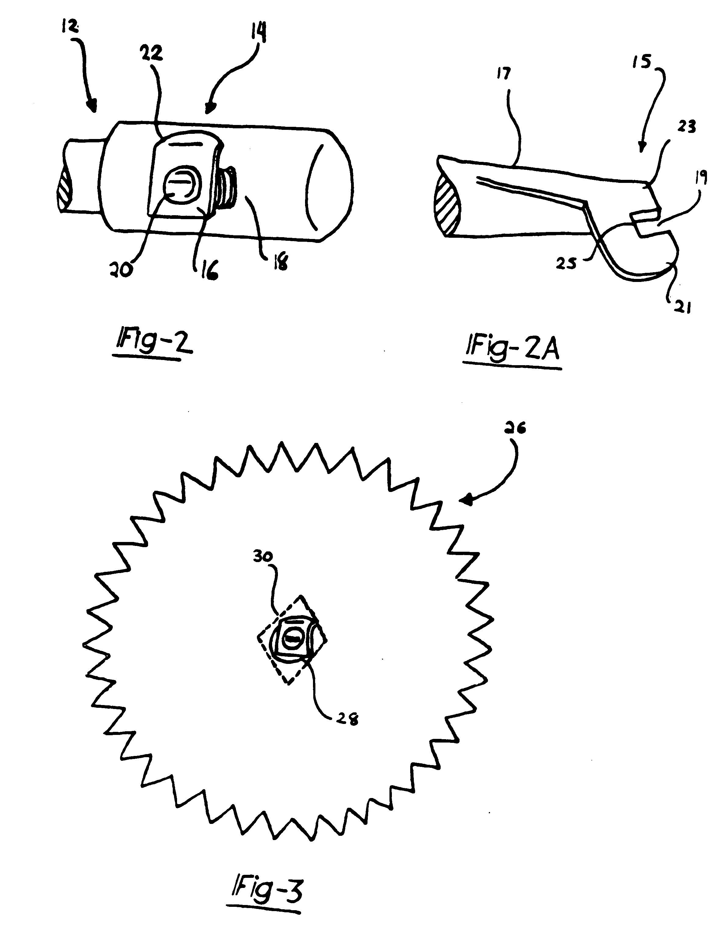
[0020]With reference to FIG. 1, an exemplary power tool 10 is shown including a hanger 12 pivotally attached to the tool to allow the hanger 12 to be moved between a use position and a non-use position. As illustrated in FIG. 1, attached to the hanger 12 is a perforated material remover 14. Although shown attached to the hanger 12, the perforated material remover 14 can be attached to any portion of the power tool 10. For example, FIG. 1A shows an alternative embodiment of a perforated material remover 15 attached to a bevel lever 17.

[0021]Turning to FIG. 2, the perforated material remover 14 can be seen more clearly. In a preferred embodiment, the perforated material remover 14 includes a body portion 16 which is...


PUM

PropertyMeasurementUnit
durabilityaaaaaaaaaa
sizeaaaaaaaaaa
dimensionsaaaaaaaaaa

Abstract

A power tool is provided with a perforated material remover to remove perforated material from power tool cutting implements. The power tool also includes a rip guide which has a long guide edge and two attachment points to the shoe / base of the saw. The rip guide is attached to the base / shoe via a pair of L-shaped openings that accept L-shaped support arms of the rip guide. The rip guide can also be folded for compact storage. The power tool also includes dual bevel scales for quickly and easily setting the bevel angle on the power tool.

Description

FIELD OF THE INVENTION[0001]The present disclosure relates to various improvements for power tools, and particularly to a perforated material remover, a saw rip guide, and bevel scales.BACKGROUND AND SUMMARY OF THE INVENTION[0002]The statements in this section merely provide background information related to the present disclosure and may not constitute prior art.[0003]One aspect of the present invention includes an accessory that provides the user with functionality to quickly and easily remove perforated material from the power tool cutting element. Certain portable tool spindles have non-standard attachment interfaces preventing the attachments of standard cutting elements. To accommodate non-standard attachment interfaces, certain cutting elements have perforations that will change the standard attachment on the cutting element to one that will match the non-standard spindle. The present disclosure includes a perforated material remover that provides the user with functionality ...

Claims


Application Information

Patent Timeline
Patent Type & Authority Applications(United States)
IPC IPC(8): B27B9/00B27B9/04
CPCB27B9/02B26B25/00B27B9/04
Inventor NICKELS, JR., RICHARD C.WIKLE, DAVID L.BOWMAN, TIMPARKS, JAMES R.BIGDEN, JONATHAN D.PECK, JEFFREYCHENG, MEI LINGCHAING, HUNG JUNGHUANG, CHUN CHIEH
Owner BLACK & DECKER INC
Learn More