
Bottle cap having filling function

Inactive Publication Date: 2009-08-20
LEEDON INT
View PDF4 Cites 40 Cited by
  • Summary
  • Abstract
  • Description
  • Claims
  • Application Information

AI Technical Summary

Benefits of technology

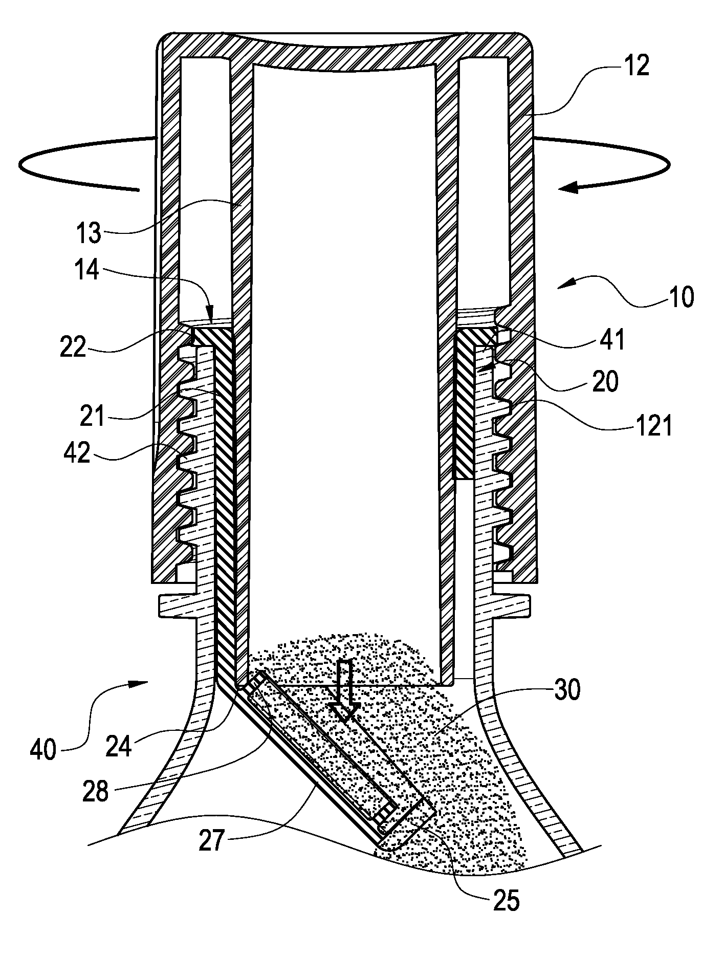
[0014]Secondly, the invention is to provide a bottle cap having a filling function for an object to be brewed and interconnected to a container's spout. According to the invention, the object to be brewed that is stored in a storage room is separated from a solution contained in the container, both of which can be blended when a drink is needed to make. Under such arrangement, a freshness of the drink may be maintained.
[0015]Thirdly, the invention is to further provide a bottle cap having a filling function. According to the invention, by means of a structure of bended edge and sectional trough, the bottle cap may be reused to achieve a double benefit of cost saving and environmental protection.

Problems solved by technology

Firstly, since the outer cover cap is inter-screwed with the top cap, the top cap is easily loosened to cause a leakage of the object to be brewed when any vibration is occurred in a transporting process. More seriously, the top cap will be moved down to make the top pillar open the sealing membrane to mix the object to be brewed with the solution.
Secondly, since the sealing membrane is arranged under the storage room by a pasting method, the membrane is easily dropped into the solution entirely when the cap pillar is abutted the sealing membrane downwardly.
Thirdly, since the sealing membrane is sealed by a pasting method, it is impossible to reuse the bottle cap having storage room according to the prior arts. If a reuse is needed, the user has to prepare a totally new sealing membrane for a sealing purpose.
However, there are many problems that still can not be solved by this kind of bottle cap having storage room, for example: 1) the sealing membrane could be dropped into the solution; 2) it is unable to be reused; and, 3) it is a little dangerous to use a structure like s ringed blade.

Method used


Image

  • Bottle cap having filling function
  • Bottle cap having filling function
  • Bottle cap having filling function

Examples


Embodiment Construction

[0024]In cooperation with attached drawings, the technical contents and detailed description of the present invention are described thereinafter according to a preferable embodiment, being not used to limit its executing scope. Any equivalent variation and modification made according to appended claims is all covered by the claims claimed by the present invention.

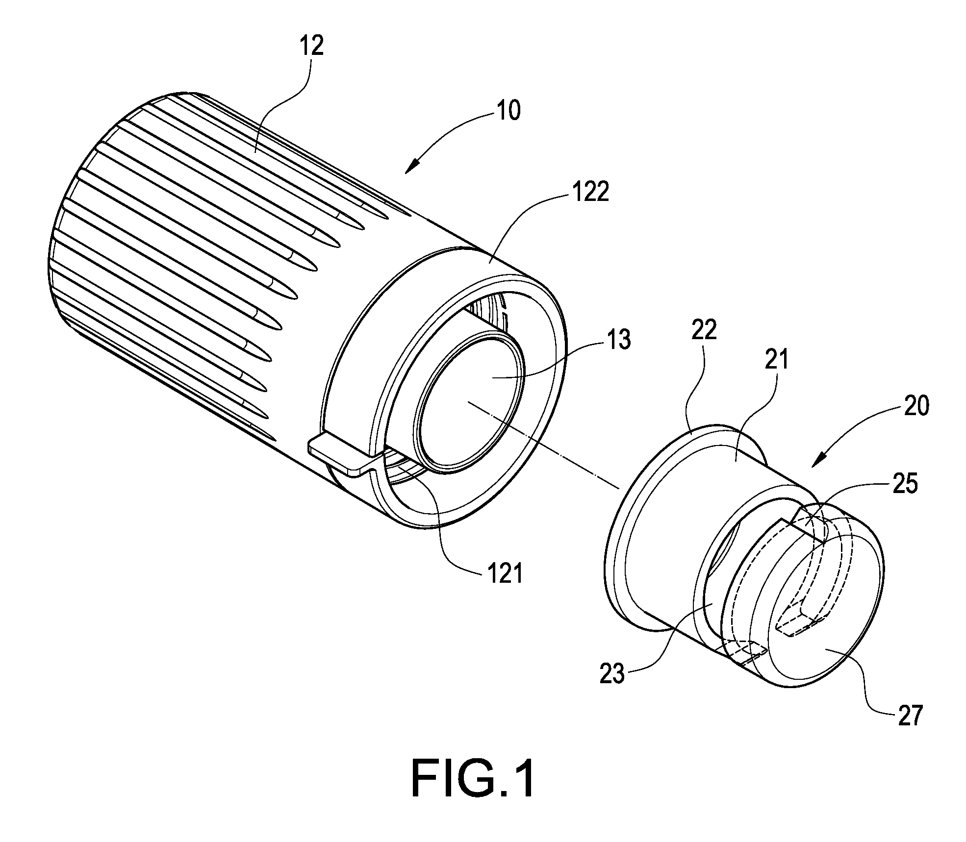
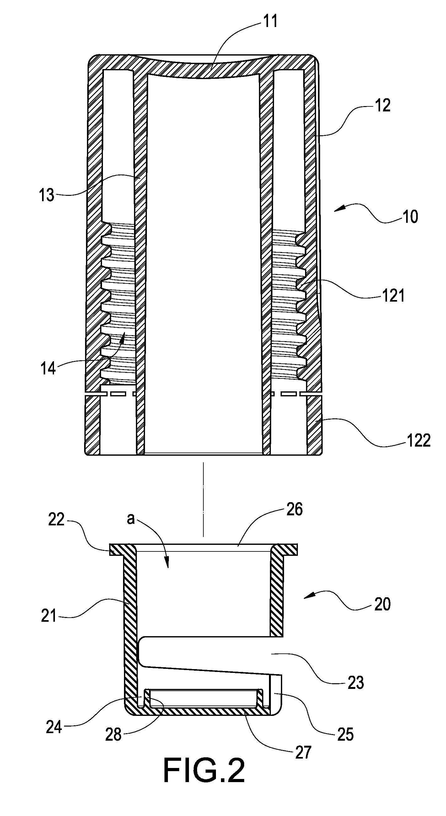
[0025]Please refer to FIG. 1 and FIG. 2, which respectively are an explosively perspective view and an explosively sectional view according to the present invention. Basically, the invention is interconnected to a container's spout (not shown in the figure) to provide a filling function for an object to be brewed, for example, tea leaf, coffee powder, and milk powder. The bottle cap includes an outer cover cap 10 and an inner sleeve 20.

[0026]The outer cover cap 10 has a top plate 11, an outer ring body 12 and an inner ring body 13, both of which are extended from the top plate 11, and between which a spacing room 14 is form...


PUM


Abstract

A bottle cap having a filling function for an object to be brewed is interconnected to a container's spout, including an outer cover cap and an inner sleeve, in which the outer cover cap has a top plate, an outer ring body and an inner ring body, both of which are extended from the top plate, and between which a spacing room is formed. According to the invention, the inner sleeve is fitted to an outer circumferential edge of the inner ring body, such that a storage room for storing an object to be brewed is formed between the inner ring body and the inner sleeve having a bended edge abutted against a side face of the spout. In addition, a sectional trough is arranged at one side far away the bended edge of the inner sleeve. Thereby, when the outer cover cap moves toward the container, the storage room will be opened to make the object to be brewed automatically filled into the container.

Description

BACKGROUND OF THE INVENTION[0001]1. Field of the Invention[0002]The present invention generally relates to a bottle cap, in particular, to a bottle cap having a filling function.[0003]2. Description of Prior Art[0004]Basically, a bottle cap having storage room can separately store an object to be brewed and a solution before blending them together to make a drink. Under such structural arrangement, the drink's freshness can be maintained and the expiration date can be prolonged.[0005]According to prior arts, a bottle cap having storage room includes an outer cover cap and a top cap, in which an interior of the outer cover cap has a storage room, which is for storing an object to be brewed, and a bottom part of which is sealed by a sealing membrane. In this case, the top cap screwed above the outer cover cap is internally abutted by a top pillar. When using, the top cap is rotated to move down the top pillar that is then abutted against the sealing membrane. After the sealing membran...

Claims


Application Information

Patent Timeline
IPC IPC(8): A47J31/44B65D41/38
CPCB65D51/2878
Inventor LIN, SHENG-CHI
Owner LEEDON INT
Learn More