Fryer

a fryer and batter technology, applied in the field of fryers, can solve the problems of contaminating food, darkening the color of food, and the conventional fryer cannot easily collect deep-fried batter balls, and achieve the effects of short time, short time, and preventing oil degradation

Inactive Publication Date: 2008-02-21
MERMAID +1
View PDF9 Cites 19 Cited by
  • Summary
  • Abstract
  • Description
  • Claims
  • Application Information

AI Technical Summary

Benefits of technology

[0039] The fryer of this invention employs the construction in which air heated by the heat accumulation unit communicating with the heat exchange pipe is introduced or discharged by the fan to adjust the temperature of the cooking oil. This construction allows the temperature of the cooking oil to go down to a low temperature in a short time, preventing degradation of the oil that is standing by for cooking. Further, by applying the heat accumulated in the heat accumulation unit to the cooking oil, the cooking oil can be returned to a high cooking temperature in a short time, facilitating the work and putting the heat to an effective use.
[0040] With the fryer of this invention, since the electrostatic dust collecting plate is installed in the oil layer, superfine solid particles are adsorbed by the electrostatic dust collecting plate. The cooking oil cleared of impurities is recirculated into the cooking oil layer. Thus the degradation of cooking oil can be minimized, reducing the frequency of oil replacement, which is economical.
[0041] With the fryer of this invention, since the interior of the cover of the oil tank is communicated with the cleaning tank and smoke produced from the oil surface is drawn by the fan and passed through the water layer, the air can be efficiently removed of smoke, smell and oil mist, improving the work environment.
[0042] With the fryer of this invention, since the water cooled by the cooling fan installed at the bottom of the water tank is drawn along with impurities such as deep-fried batter balls into the filter water tank, from which the filtered water is returned to the water tank, the time during which the cooking oil is kept at an elevated temperature is shortened, minimizing the degradation of oil, maintaining the clarity and freshness of the cooking oil. There is also an advantage that the water can be filtered in the filter water tank along with the impurities.
[0043] With the fryer of this invention, since the mixing prevention grid is installed near a boundary between the water layer and the oil layer, the mixing of water and cooking oil, which would otherwise be caused by the rising cooking oil released from the bottom of the water tank or by the release of water, can be prevented.
[0044] With the fryer of this invention, since the dispersion plate to scatter around the cooking oil rising through the water layer is installed in a path in which the cooking oil released from the bottom of the water tank rises, the cooking oil that has passed through the water layer can be prevented from quickly rising through the low-temperature oil layer to the cooking oil layer. This offers an advantage of being able to maintain a good cooking environment for the oil.

Problems solved by technology

The conventional fryer cannot easily collect deep-fried batter balls that disperse from food ingredients into the cooking oil during the frying process, colloidal materials drifting away from the food being fried, and impurities including water, smell and fat flowing out of the food material.
These unwanted materials that stay long in the cooking oil cause early degradation of the oil and darken its color, which in turn contaminate the food.
This accelerates degradation and oxidation of the cooking oil, increases oil smoke and evaporation, and rapidly changes the composition of the oil.
As a result, the conventional fryer needs to replace the cooking oil frequently, giving rise to a problem of a high economic burden.
This in turn darkens the oil and over time degrades its quality.
However, this removal work is difficult considering the convenience of the frying process and the construction of the fryer.
The water discharged into the atmosphere turns into smoke and, along with the oil, into oil mist, contaminating the interior of the kitchen and equipment.
Further, the water released into the cooking oil mixes with the oil over time, contributing to oxidation and degradation of the oil.
If this process is continued, there is a risk of the oil flowing over the oil tank.
With this means, however, the water released into the oil cannot be removed sufficiently.
It is also difficult to perform the cleaning each time the fryer is used.
This deteriorates the cooking oil and shortens its life, leading to the frequent replacement of the oil.
Furthermore, this mode of operation necessarily consumes heat energy wastefully for many hours.
Many, large and small deep-fried batter balls coming off the food are dispersed in oil layers and are difficult to remove completely with an existing removal net.
It is even more difficult to remove them during the frying process.
This, however, takes time and is practically impossible as a means to be performed during the frying process.
As a result, the deep-fried batter balls are left in the cooking oil for many hours, shortening the life of the oil.
Although the volume of their release decreases when foods are not being fried, smoke and oil mist are always rising.
A dedicated exhaust device installed above the fryer cannot discharge them sufficiently, leaving smell and possible environmental contaminations.
In addition, there are lots of fine particles of these unwanted materials.
Therefore they cannot be collected quickly, which in turn shortens the life of the oil, giving rise to an economic problem.
As described above, leaving the unwanted deep-fried batter balls in the hot cooking oil for many hours causes smells, smoke and oil mist to adhere to equipment and human body, polluting the environment.

Method used


Image

  • Fryer
  • Fryer
  • Fryer

Examples


Embodiment Construction

[0049] Now, preferred embodiments of the present invention will be described.

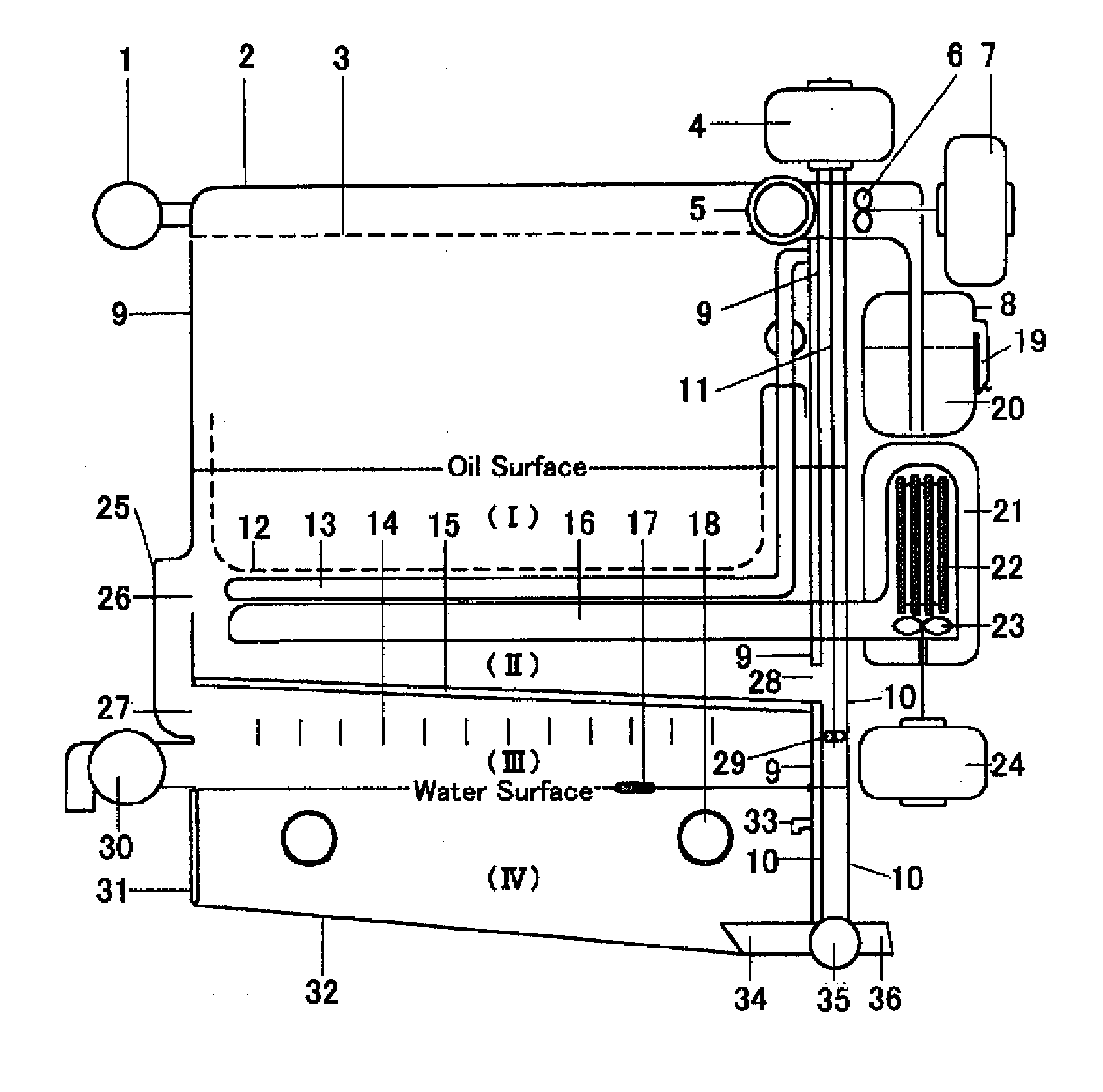
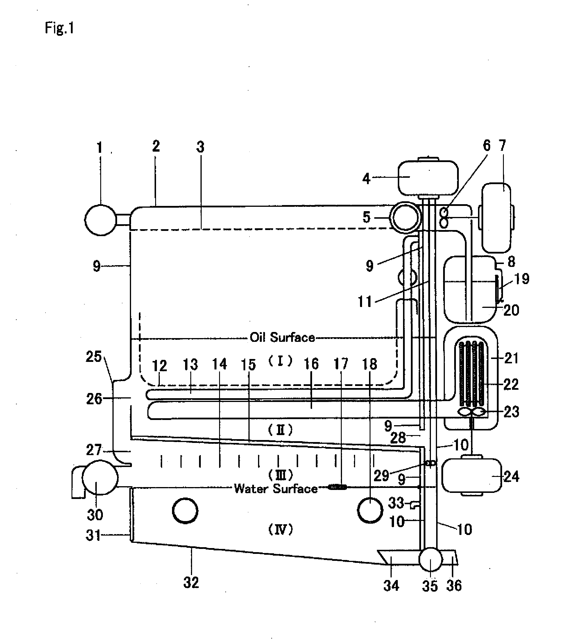
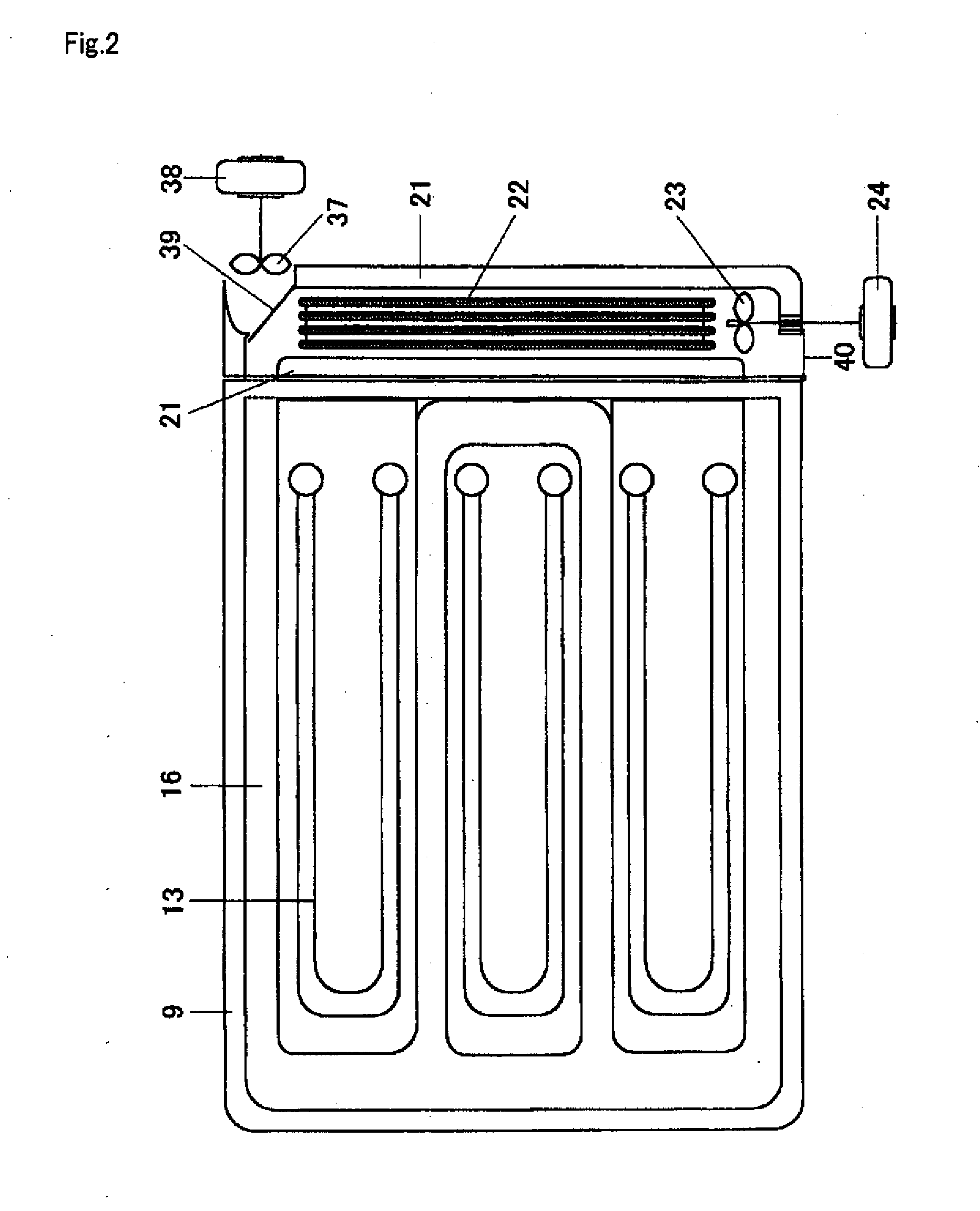
[0050]FIG. 1 and FIG. 2 illustrate a fryer according to a first embodiment of this invention. FIG. 1 is an explanatory side view of the fryer. Denoted 9 is an oil tank 9, 32 a water tank 32, and 13 an electric heater 13 to heat cooking oil in the oil tank. In the oil tank 9 there are formed a high-temperature cooking oil layer (I) above the heater 13 and a low-temperature oil layer (II) below the heater 13. Below the low-temperature oil layer (II) is installed a partition plate 15. Below the oil tank 9 is provided the water tank 32. Between a water layer (IV) in this water tank 32 and the partition plate 15 there is formed an oil storage layer (III) to store oil.

[0051] A temperature sensor (not shown) is installed in the frying oil layer (I) to maintain the oil temperature. When the oil temperature falls below a set level, the heater 13 is turned on to start heating to keep the oil at the set temperature....


PUM


Abstract

A fryer for business use is provided which can prevent degradation of cooking oil, secure a good cooking environment and improve a work efficiency. To this end, the fryer of this invention comprises: a water tank 32, 82 to store water; an oil tank 9, 51 arranged above the water tank to store the cooking oil in contact with the stored water in the water tank; a heater 13, 52 arranged in an oil layer in the oil tank; and an oil delivery pipe 10, 61 through which to draw the cooking oil in the oil layer by a pump 29, 64 and release it onto a bottom of the water tank 32, 82; wherein the released cooking oil rises through the water layer and flows into a lower part of the oil layer.

Description

TECHNICAL FIELD [0001] The present invention relates to a fryer mainly used for business purposes and more particularly to a fryer equipped with a device for automatically removing deep-fried batter balls and an automatic cooking oil cleaning device to keep the cooking oil clean, prevent its degradation and thereby extend its useful life. BACKGROUND ART [0002] Conventional fryers store a specified amount of cooking oil in an oil tank and heat it with a gas or electric heater. With the cooking oil heated to a set temperature, the fryer stands by and food materials are thrown in for frying. After a predetermined cooking time, the fried food is taken out and put on paper or an oil draining pan to remove excess oil. Now the frying operation is complete. [0003] Therefore, with the conventional fryer the cooking oil remains at high temperatures continuously even when no frying operation is performed. [0004] The conventional fryer cannot easily collect deep-fried batter balls that disperse...

Claims


Application Information

Patent Timeline
Patent Type & Authority Applications(United States)
IPC IPC(8): A47J37/12
CPCA47J37/1285A47J37/1257
Inventor USUI, RIEKIMURA, TAKAOSHIBASAKI, KUNIO
Owner MERMAID
Why Eureka
Try Eureka