Method and apparatus for artificial disc insertion
What is AI technical title?
AI technical title is built by Patsnap AI team. It summarizes the technical point description of the patent document.
a technology of artificial discs and insertion devices, applied in the field of methods and apparatus can solve the problems of surgical techniques and procedures that do not always work reliably for artificial disc insertion, and achieve the effect of reliably correcting alignment and reliable alignmen
Inactive Publication Date: 2006-07-27
HAWKINS JOHN RILEY +9
View PDF14 Cites 133 Cited by
Summary
Abstract
Description
Claims
Application Information
AI Technical Summary
This helps you quickly interpret patents by identifying the three key elements:
Problems solved by technology
Method used
Benefits of technology
Benefits of technology
[0012] Artificial discs offer several theoretical benefits over spinal fusion for chronic back pain, including pain reduction and a potential to avoid premature degeneration at adjacent levels of the spine by maintaining normal spinal motion. However, like spinal fusion surgery, surgical techniques and procedures do not always work reliably for artificial disc implantation. Thus, there remains a need for improved instrumentation and techniques for disc space preparation and artificial disc implantation.
[0023] The invention has many advantages. For example, the invention provides reliably correct alignment for preparing a disc space of artificial disc implantation. The invention also provides the reliably correct alignment for artificial disc insertion into the prepared disc space.
Problems solved by technology
While there have been significant advances in spinal fusion devices and surgical techniques, the procedure does not always work reliably.
However, like spinal fusion surgery, surgical techniques and procedures do not always work reliably for artificial disc implantation.
Method used
Image
Click on the blue label to locate the original text in one second.
Reading with bidirectional positioning of images and text.
Examples
Embodiment Construction
[0088] The foregoing and other objects, features and advantages of the invention will be apparent from the following more particular description of preferred embodiments of the invention, as illustrated in the accompanying drawings in which like reference characters refer to the same parts throughout the different views. The same number appearing in different drawings represents the same item. The drawings are not necessarily to scale, with emphasis instead being placed upon illustrating the principles of the invention.
[0089] In general, the surgical procedure for implantation utilizes an anterior approach. During the surgery, a small incision is made in the abdomen below the belly button. The organs are carefully moved to the side so the surgeon can visualize the spine. The surgeon then removes a portion of a disc. In one embodiment, the implant is inserted; endplates first followed by the polyethylene core. The disc stays in place from the tension in spinal ligaments and the rema...
PUM
Abstract
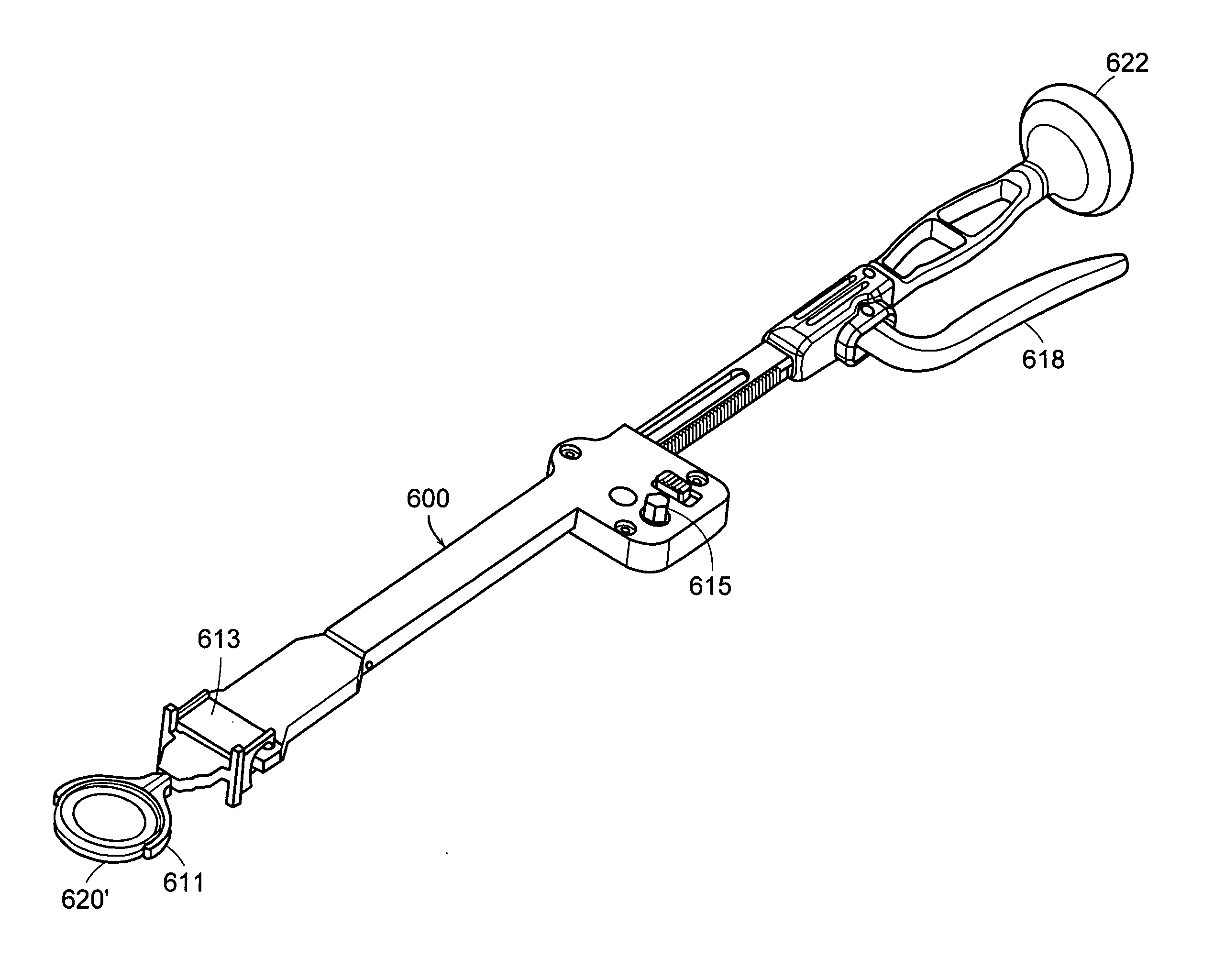
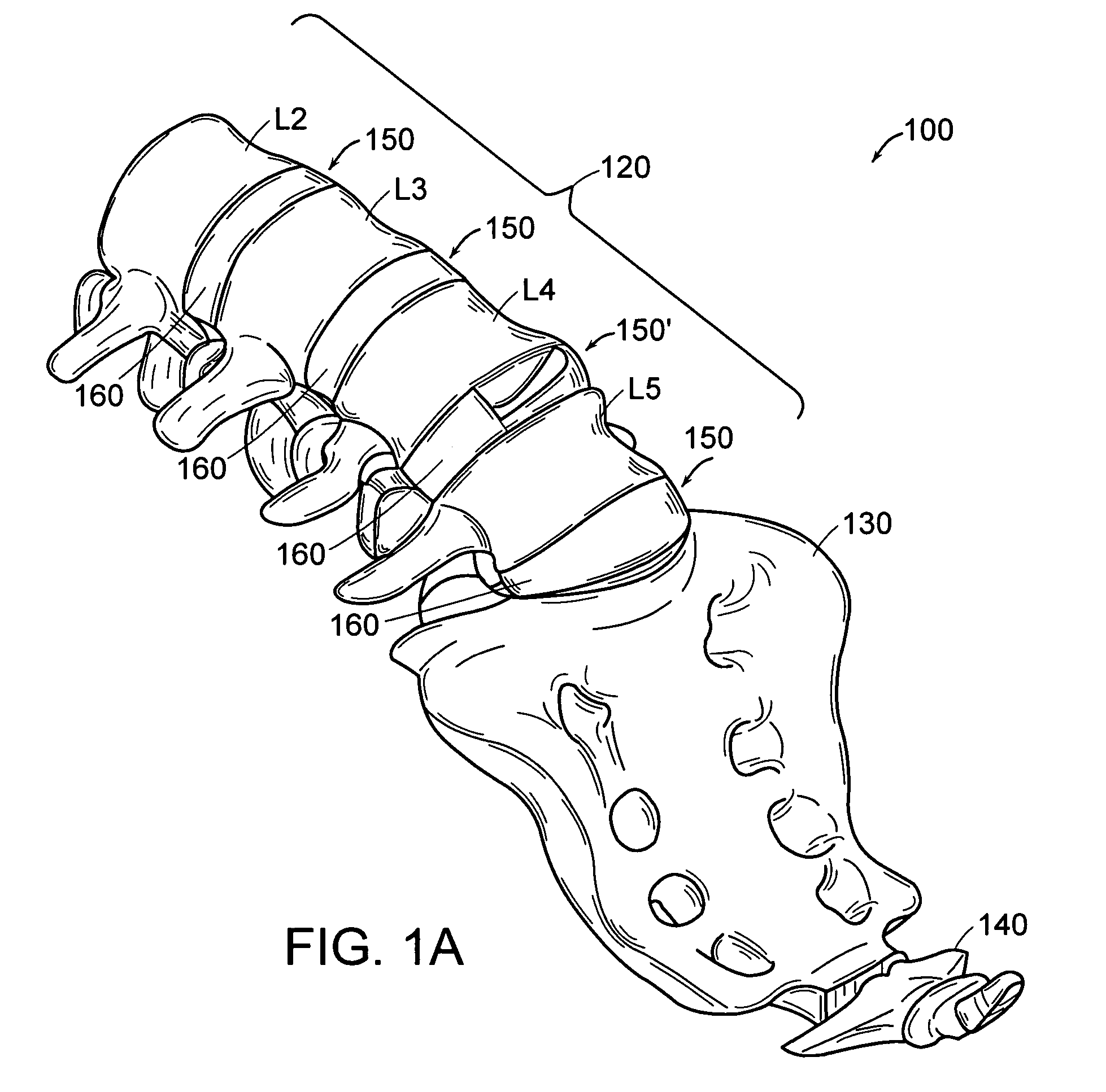
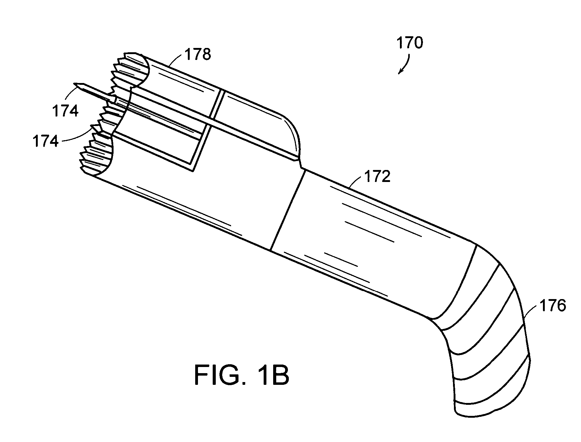
An anterior method for implanting an artificial disc in an intervertebral space of a human body includes inserting a midline marker in a face of a vertebral body for instrument alignment and artificial disc placement. A kit for implanting an artificial disc in an intervertebral space of a human body includes site preparation instruments, artificial disc insertion instruments, and a midline marker for guiding the artificial disc insertion instruments into a prepared intervertebral space. Also included are a verification instrument, a midline marker, a midline marker insertion instrument, an endplate shaping device, a distraction instrument, a trial insertion instrument, an endplate insertion instrument, a core insertion instrument, and a trial spacer head.
Description
RELATED APPLICATION(S) [0001] This application is a divisional of U.S. application Ser. No. 10 / 813,899, filed Mar. 31, 2004, which claims the benefit of U.S. Provisional Application No. 60 / 459,280 filed Mar. 31, 2003, which is related to U.S. patent application Ser. No. 10 / 011,264, filed Dec. 7, 2001; U.S. patent application Ser. No. 10 / 200,890, filed Jul. 23, 2002, U.S. Provisional Application No. 60 / 391,628, filed Jun. 26, 2002; and U.S. Provisional Application No. 60 / 391,845, filed Jun. 27, 2002. The entire teachings of the above application(s) are incorporated herein by reference.BACKGROUND OF THE INVENTION [0002] An intervertebral disc has several important functions, including functioning as a spacer, a shock absorber, and a motion unit. [0003] The disc maintains the separation distance between adjacent boney vertebral bodies. The separation distance allows motion to occur, with the cumulative effect of each spinal segment yielding the total range of motion of the spine in sev...
Claims
Application Information
Patent Timeline
Application Date:The date an application was filed.
Publication Date:The date a patent or application was officially published.
First Publication Date:The earliest publication date of a patent with the same application number.
Issue Date:Publication date of the patent grant document.
PCT Entry Date:The Entry date of PCT National Phase.
Estimated Expiry Date:The statutory expiry date of a patent right according to the Patent Law, and it is the longest term of protection that the patent right can achieve without the termination of the patent right due to other reasons(Term extension factor has been taken into account ).
Invalid Date:Actual expiry date is based on effective date or publication date of legal transaction data of invalid patent.
Patent Type & AuthorityApplications(United States)
InventorHAWKINS, JOHN RILEYSTAD, SHAWN D.ROGERS, CHRISTOPHERGRINBERG, ALEXANDERNAUGHTON, RONALDSORRENTI, MICHAEL D.CASEY, NIALL P.GRACIA, MARKSOUZA, CARLFATYOL, PAT

