Burner with flame stability

a burner and flame stability technology, applied in the field of burners, can solve problems such as airflow disturbances that can arise, affect the stability of flames,

Active Publication Date: 2009-08-20
ELECTROLUX HOME PROD CORP NV
View PDF19 Cites 13 Cited by
  • Summary
  • Abstract
  • Description
  • Claims
  • Application Information

AI Technical Summary

Benefits of technology

[0011]In all the foregoing aspects, a burner cap can be provided for closing off the top of the burner body, including the top of the stability chamber so as to substantially preclude the escape of the combustible gas from the combustible gas chamber, the stability gas chamber and the burner ports at the top of the burner body. The burner cap can have an undersur

Problems solved by technology

One of the conditions affecting the performance of combustible gas burners concerns airflow disturbances that can arise at the burners upon the occurrence, for example, of ambient air drafts or drafts that are caused by the rapid opening and closing of doors and drawers, suc

Method used


Image

  • Burner with flame stability
  • Burner with flame stability
  • Burner with flame stability

Examples


Embodiment Construction

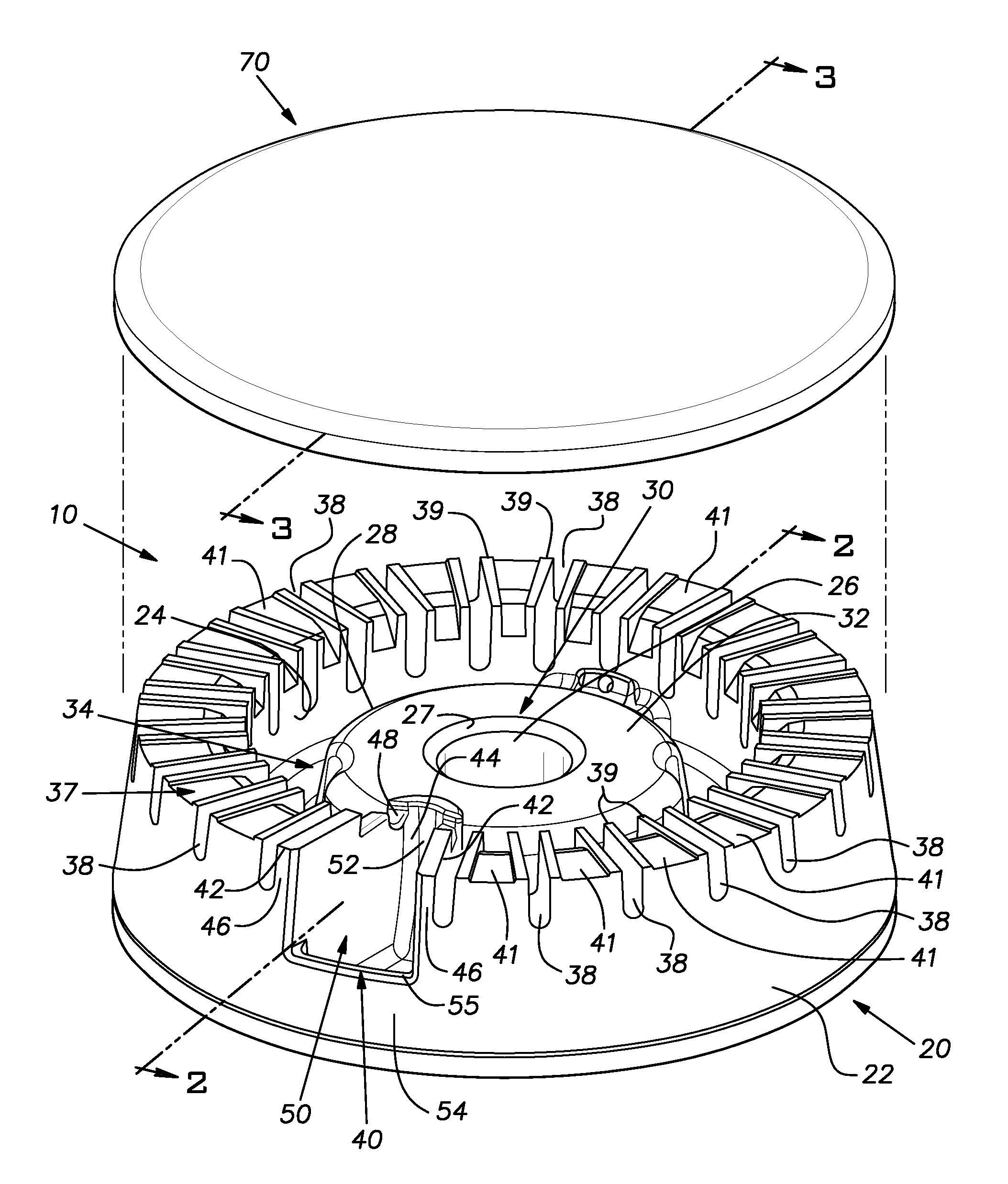
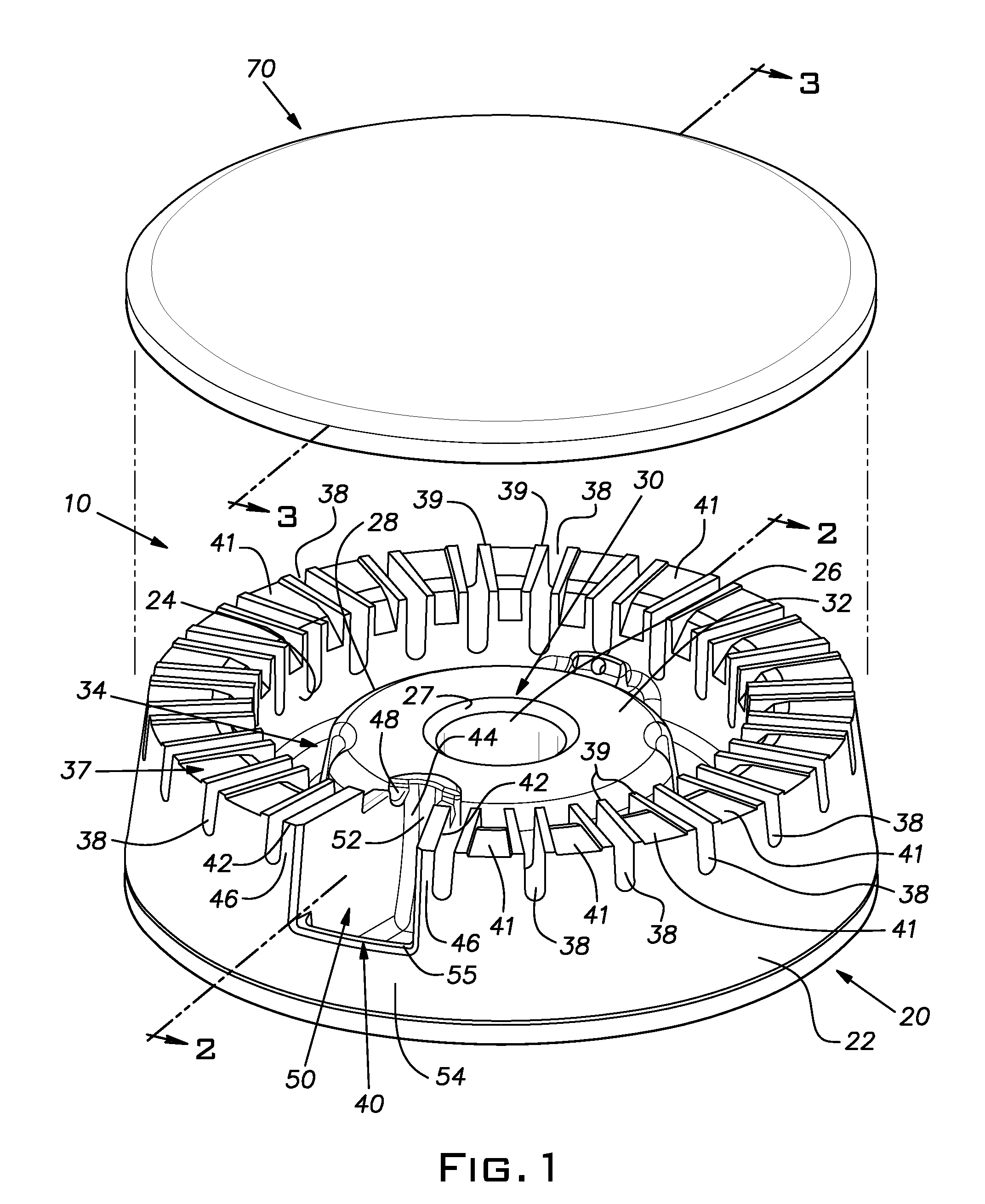
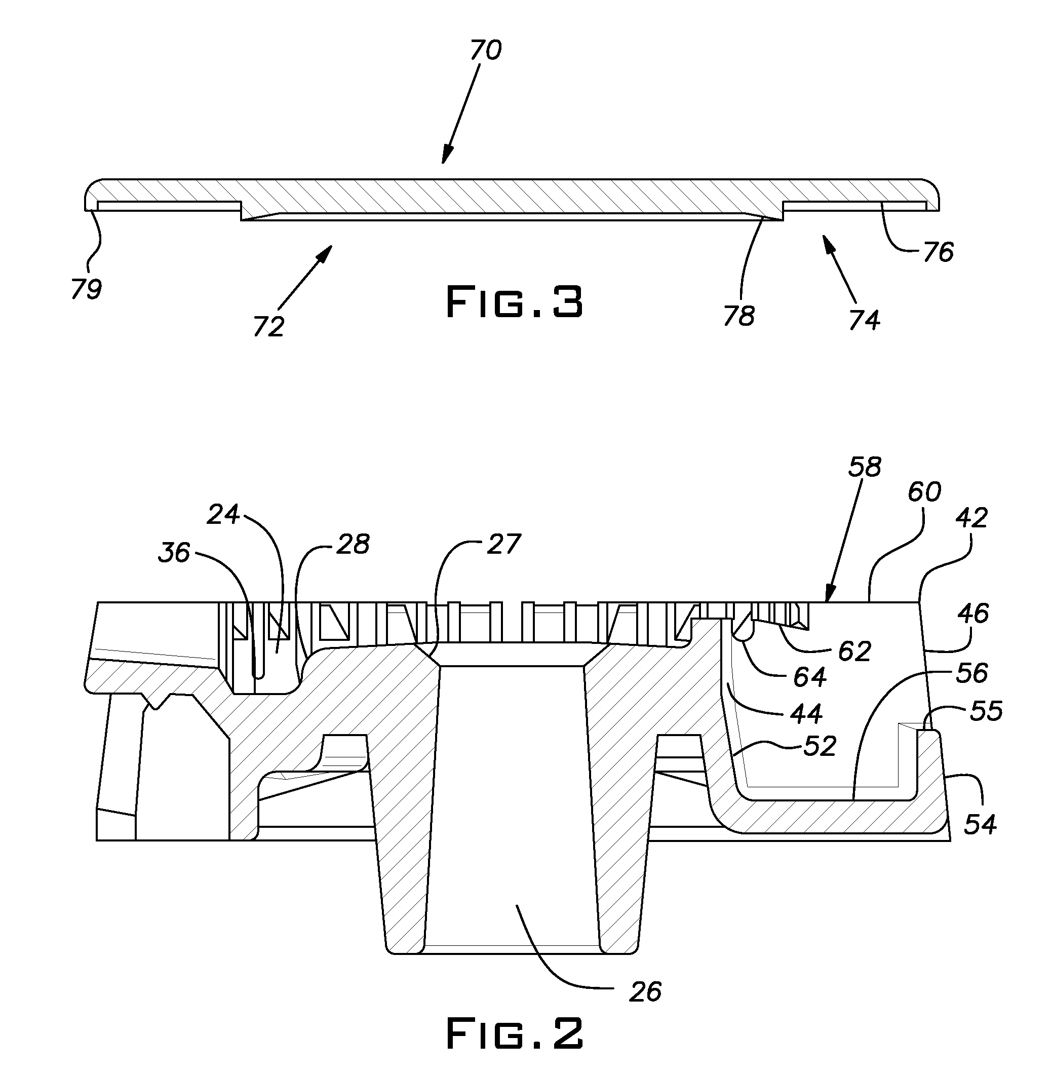
[0016]Referring to the drawings there is shown an embodiment of the burner assembly of the invention indicated generally at 10 at which a combustible gas can be combusted. The burner assembly 10 includes a burner body or burner head indicated generally at 20 and a stability chamber indicated generally at 40. The embodiment of the burner assembly shown in the drawings is illustrated as also including a cap indicated generally at 70. The burner body 20 includes an exterior surface 22 that has the general shape of a truncated cone and a first interior surface 24 that generally is cylindrical in configuration. The exterior surface 22 and the interior surface 24 girdle, on opposite sides, an annular structure indicated generally at 30. Located substantially centrally of the confines of the annular structure 30 is an annular projection indicated generally at 32 that includes an opening 26 located substantially centrally in the annular projection 32. The opening 26 is in gas flow communica...


PUM

PropertyMeasurementUnit
Angleaaaaaaaaaa
Shapeaaaaaaaaaa
Stabilityaaaaaaaaaa

Abstract

The present invention concerns a burner assembly that includes a burner body having a combustible gas chamber from which a combustible gas is distributed to a plurality of burner ports at which the combustible gas can be combusted and a stability chamber in gas-flow communication with the combustible gas chamber for maintaining the combustion of the combustible gas in the stability chamber whenever the combustion of the combustible gas at the plurality of burner ports is disturbed, whereby the combustion of the combustible gas at the plurality of the burner ports may be resumed upon the cessation of the disturbance. The burner assembly can also include a burner cap for closing off the top of the burner body so as to substantially preclude the escape of the combustible gas from the combustible gas chamber, the stability gas chamber and the burner ports at the top of the burner body.

Description

BACKGROUND OF THE INVENTION[0001]The present invention relates to burners that burn a combustible gas, and, in particular, the invention concerns burners of the type that are used in cooking appliances of various kinds.[0002]Gas burners such as gas surface burners, for example, that are used with domestic gas ranges typically include a burner body or head that includes a plurality of burner ports through which a combustible gas is distributed to the exterior of the burner body. A burner cap can be provided at the top of the burner body so as to close off the interior of the burner body to the escape of the combustible gas. Usually a mixing conduit introduces a mixture of a gaseous fuel and air as the combustible gas into the burner body. The gas-air mixture can be confined in combustible gas plenum within the burner body that is closed off by the burner cap. From the plenum, the combustible gas typically passes through the burner ports and is ignited by an igniter and burned. Often ...

Claims


Application Information

Patent Timeline
IPC IPC(8): F23D14/02F24C3/00F23D14/46
CPCF23D14/06F24C3/085F23D2207/00F23D14/26
Inventor POTTENGER, JOHNPRYOR, WILLIAM A.ARMANNI, PIEROSERENELLINI, PAULO
Owner ELECTROLUX HOME PROD CORP NV
Why Eureka
Try Eureka