Downwell system with differentially swellable packer

a technology of differential swelling and downwell system, which is applied in the direction of sealing/packing, fluid removal, borehole/well accessories, etc., can solve the problems of cement sheath debonding, limited use, and complicated construction and operation

Inactive Publication Date: 2009-08-20
STOWE WOODWARD
View PDF16 Cites 19 Cited by
  • Summary
  • Abstract
  • Description
  • Claims
  • Application Information

AI Technical Summary

Benefits of technology

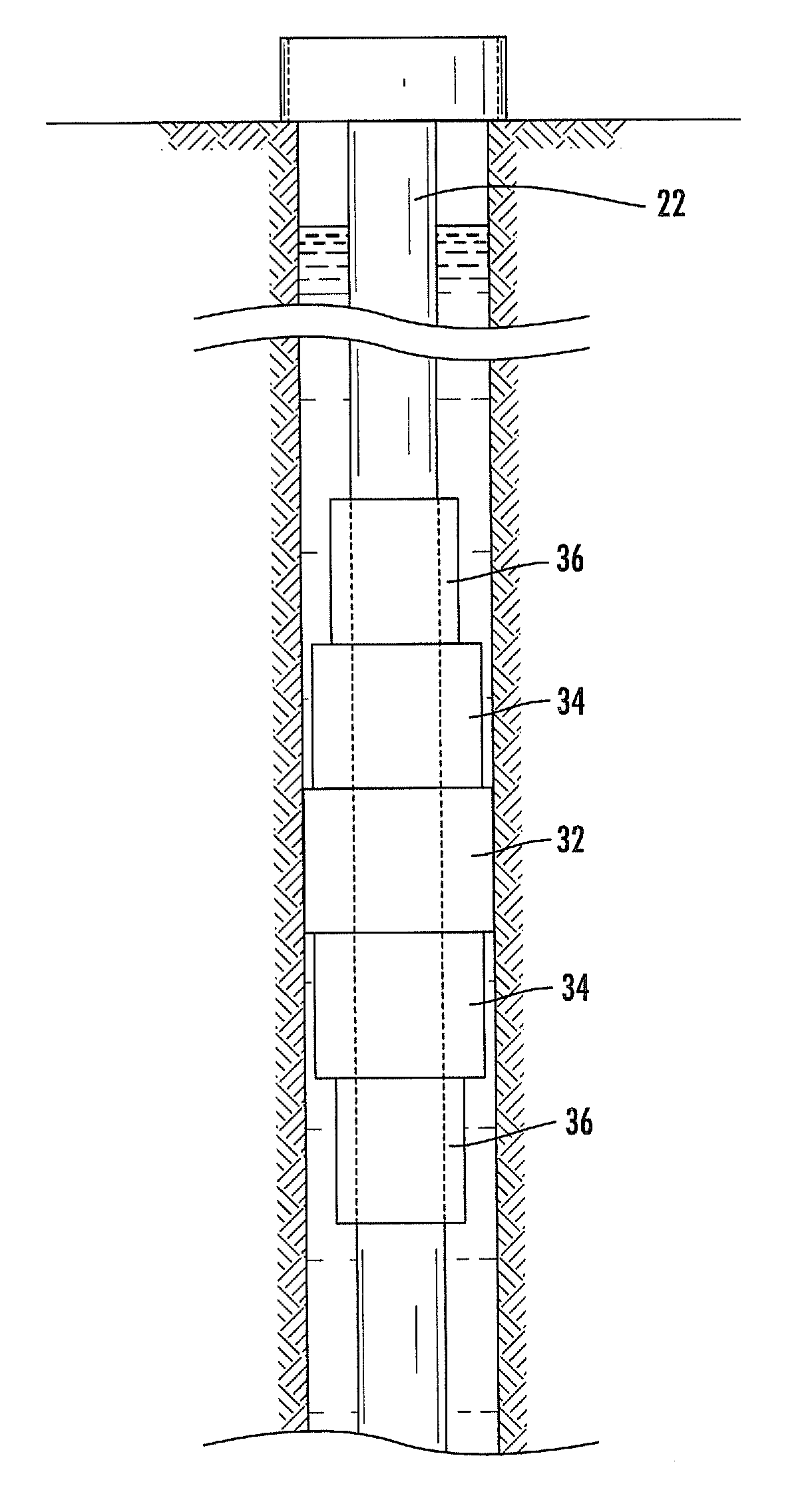
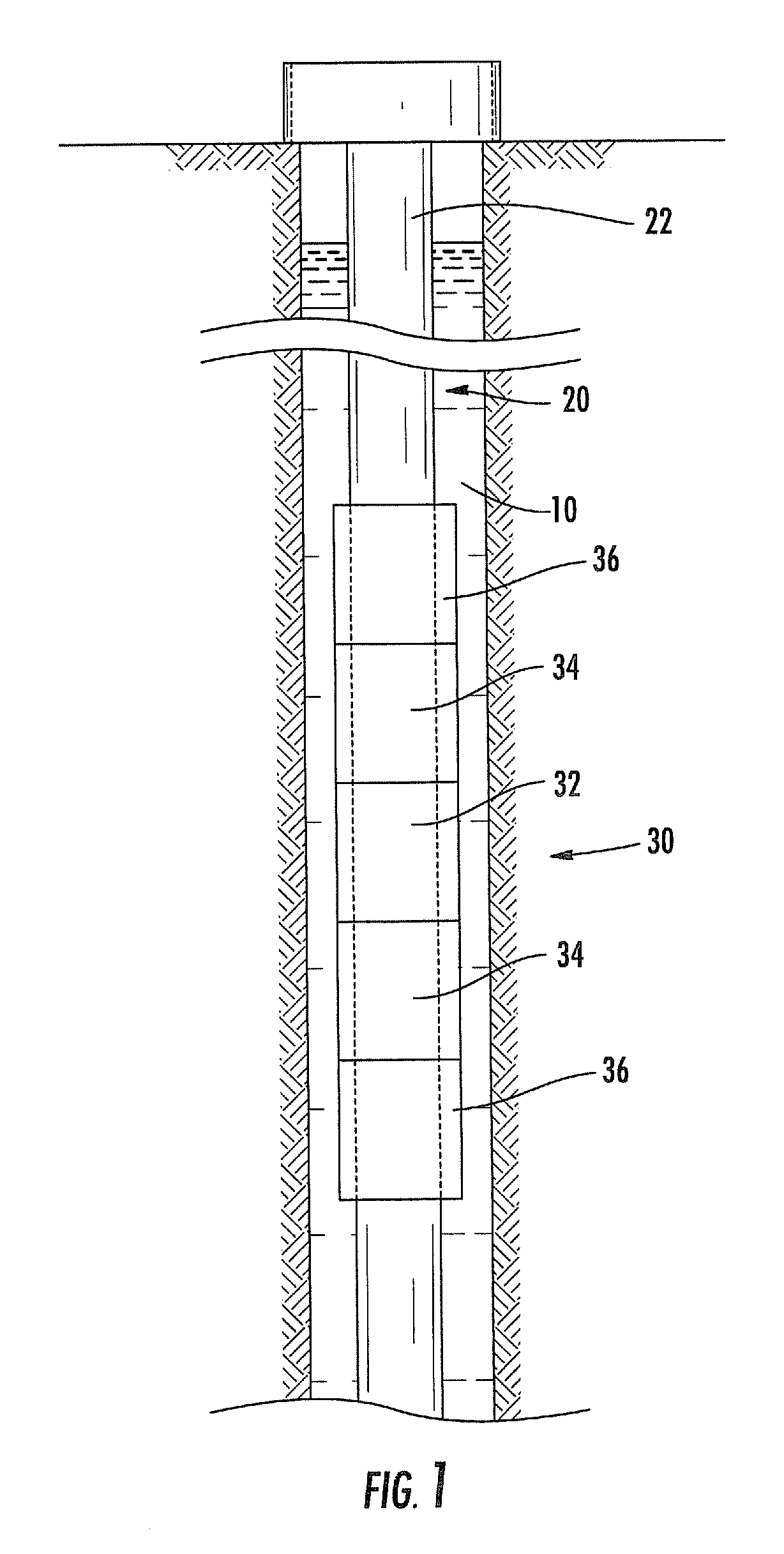
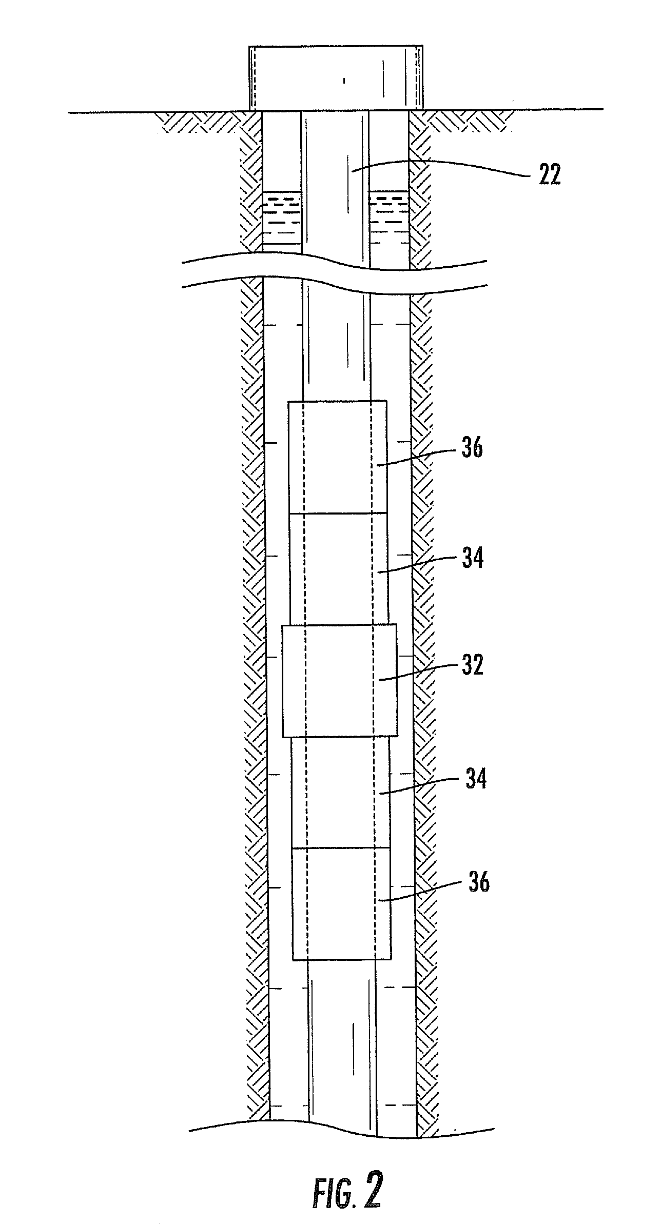
[0009]As a first aspect, embodiments of the present invention are directed to a packer assembly for a wellbore. The packer assembly comprises a tubular member and a packer system that circumferentially overlies the tubular member. The packer system includes end portions and a central portion disposed between the end portions. The central portion and the end portions are formed of material that swells when contacted with a swelling fluid. The central and end portions are constructed to swell upon contact with the swelling fluid so that the central portion swells to a diameter defined by a wall of the wellbore more rapidly than the end portions. In such a configuration, the central portion of the packer system can be fully swollen prior to the full swelling of the end portions.
[0010]As a second aspect, embodiments of the present invention are directed to a packer assembly for a wellbore comprising a tubular member and a packer system that circumferentially overlies the tubular member. The packer system includes end portions and a central portion disposed between the end portions. The central portion and the end portions are formed of material that swells when contacted with a swelling fluid. The central portion is formed of a first material, the end portions are formed of a second, different material, and the first material swells more rapidly in the swelling fluid than the second material.
[0011]As a third aspect, embodiments of the present invention are directed to a packer assembly for a wellbore comprising a tubular member and a packer system that circumferentially overlies the tubular member. The packer system includes end portions and a central portion disposed between the end portions. The central portion and the end portions are formed of material that swells when contacted with a swelling fluid. The central portion has a first diameter and the end portions have a second diameter that is less than the first diameter.

Problems solved by technology

One limitation of the applicability of such packers is that the seal surfaces typically need to be well defined, and therefore their use may be limited to wellbores with casings.
Also, they can be somewhat complicated and intricate in their construction and operation.
Although in general cement provides adequate sealing capability, there are some inherent drawbacks such as shrinking of the cement during hardening, which can result in de-bonding of the cement sheath, or cracking of the cement layer after hardening.
Although swellable systems are relatively inexpensive and simple, it can be difficult to control the timing of expansion of different sections of the packer.
For example, if the ends of the packer seal prior to the center, it may be difficult or impossible for swelling fluid to reach the center portion of the packer.
Incomplete swelling of the central portions of the packer can cause a delay in time to full set and / or a reduced capability to seal differential pressures.

Method used


Image

  • Downwell system with differentially swellable packer
  • Downwell system with differentially swellable packer
  • Downwell system with differentially swellable packer

Examples


Embodiment Construction

[0020]The present invention will now be described more fully hereinafter, in which preferred embodiments of the invention are shown. This invention may, however, be embodied in different forms and should not be construed as limited to the embodiments set forth herein. Rather, these embodiments are provided so that this disclosure will be thorough and complete, and will fully convey the scope of the invention to those skilled in the art. In the drawings, like numbers refer to like elements throughout. Thicknesses and dimensions of some components may be exaggerated for clarity.

[0021]Unless otherwise defined, all terms (including technical and scientific terms) used herein have the same meaning as commonly understood by one of ordinary skill in the art to which this invention belongs. It will be further understood that terms, such as those defined in commonly used dictionaries, should be interpreted as having a meaning that is consistent with their meaning in the context of the releva...


PUM


Abstract

A packer assembly comprises a tubular member and a packer system that circumferentially overlies the tubular member. The packer system includes end portions and a central portion disposed between the end portions. The central portion and the end portions are formed of material that swells when contacted with a swelling fluid. The central and end portions are constructed to swell upon contact with the swelling fluid so that the central portion swells to a diameter defined by a wall of the wellbore more rapidly than the end portions. In such a configuration, the central portion of the packer system can be fully swollen prior to the full swelling of the end portions.

Description

RELATED APPLICATION [0001]The present application claims priority from U.S. Provisional Patent Application Ser. No. 61 / 028,940, filed Feb. 15, 2008, the disclosure of which is hereby incorporated herein in its entirety.FIELD OF THE INVENTION [0002]The present invention relates generally to a wellbore system for oil exploration, and more particularly to a packer for a wellbore system.BACKGROUND OF THE INVENTION [0003]A downhole wellbore system typically includes a pipe or other tubular structure that extends into a borehole drilled into the ground. In some instances, a casing is inserted into the wellbore to define its outer surface; in other instances, the rock or soil itself serves as the wall of the wellbore.[0004]Many wellbore systems include a packer, which is designed to expand radially outwardly from the pipe against the walls of the wellbore. The packer is intended to seal segments of the pipe against the wellbore in order to isolate some sections of the wellbore from others....

Claims


Application Information

Patent Timeline
Patent Type & Authority Applications(United States)
IPC IPC(8): E21B33/12E21B33/127
CPCE21B33/1208
Inventor GUSTAFSON, ERIC J.BUTTERFIELD, WILLIAM S.WILLIAMSON, PETER
Owner STOWE WOODWARD
Why Eureka
Try Eureka