Ink jet recording apparatus and ink jet recording method
a recording apparatus and ink jet technology, applied in the direction of printing, other printing apparatus, etc., can solve the problems of low production efficiency, large apparatus, high cost, etc., and achieve the effect of hardening uv ink, improving wettability, and improving wettability
- Summary
- Abstract
- Description
- Claims
- Application Information
AI Technical Summary
Benefits of technology
Problems solved by technology
Method used
Image
Examples
second embodiment
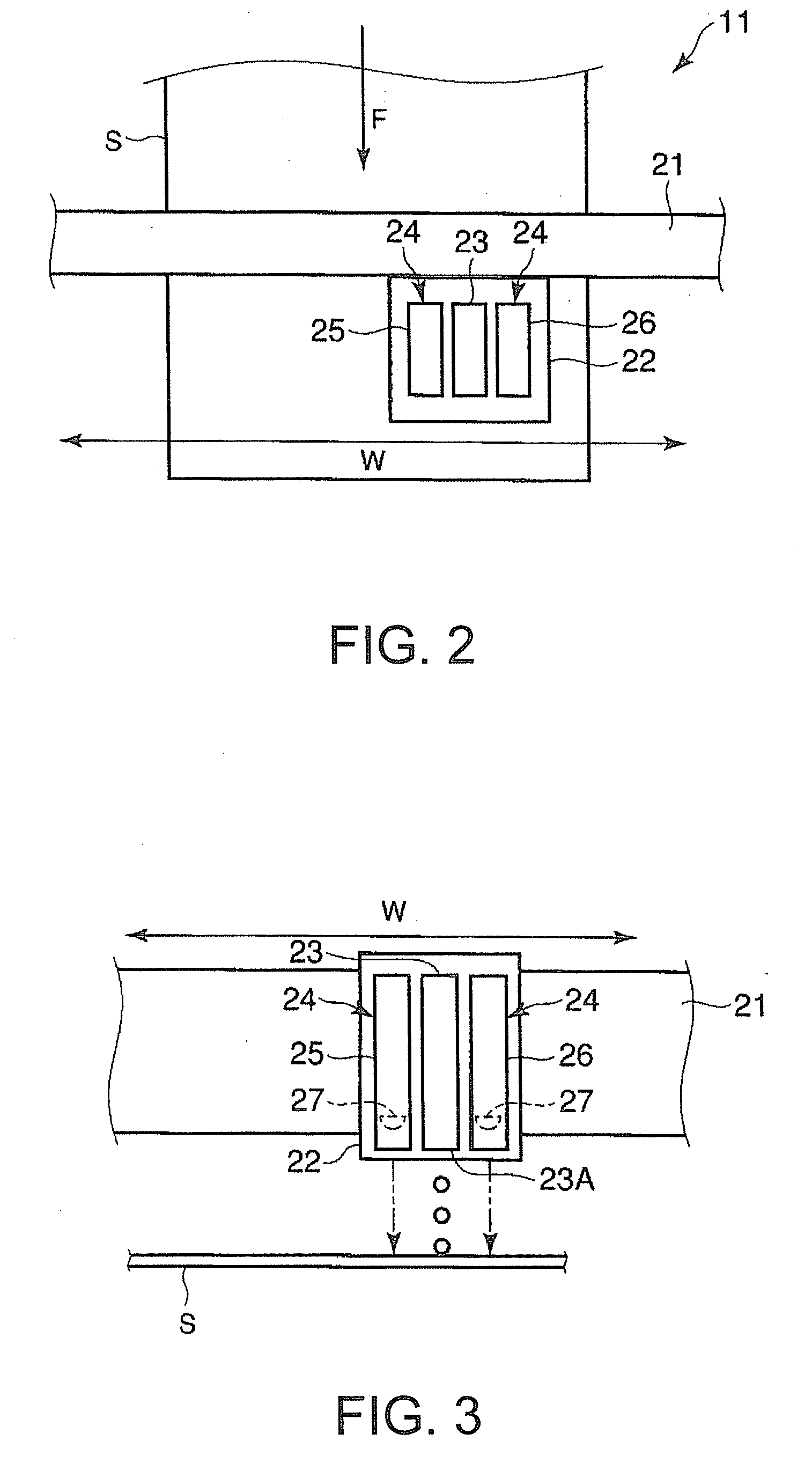
[0042] even if the ink jet head 23 has a line type constitution, the surface reforming before printing and hardening of UV ink after printing can be realized by the UV irradiation device 24.
[0043]Then, by referring to FIG. 8, the third embodiment of an ink jet recording apparatus 41 will be explained. The ink jet recording apparatus 41 of the third embodiment has a different constitution of a first unit 42 and a second unit 43 of the UV irradiation device 24 from that of the first embodiment, though the other portions are common. Therefore, the portions different from those of the first embodiment will be explained mainly and to the portions common to the first embodiment, the common numerals are assigned and the explanation thereof will be omitted.
third embodiment
[0044]The UV irradiation device 24 of the ink jet recording apparatus 41 relating to the third embodiment includes the first unit 42 and second unit 43. The first unit 42 and second unit 43, in the feeding direction F of the sheet S, is formed longer than the length of the ink jet head 23.
[0045]The first unit 42 and second unit 43 of the UV irradiation device 24 respectively include corresponding portions 42A and 43A corresponding to the ink jet head 23 in the feeding direction F and projecting portions 42B and 43B off the ink jet head 23 in the feeding direction F. The projecting portions 42B and 43B are arranged on the upstream side of the ink jet head 23 in the feeding direction F.
[0046]According to the third embodiment, prior to printing by the ink jet head 23, a lot of time can be put in the surface reforming of the sheet S. Therefore, when printing on the sheet S taking a lot of time in the surface reforming or on a metallic sheet, a plastic sheet, or a film which are a printe...
fourth embodiment
[0048]The UV irradiation device 24 of the ink jet recording apparatus 51 relating to the fourth embodiment includes the first unit 52 and second unit 53. The first unit 52 and second unit 53, in the feeding direction F of the sheet S, is formed longer than the length of the ink jet head 23.
[0049]The first unit 52 and second unit 53 of the UV irradiation device 24 respectively include corresponding portions 52A and 53A corresponding to the ink jet head 23 in the feeding direction F and projecting portions 52B and 53B off the ink jet head 23 in the feeding direction F. In the fourth embodiment, unlike the third embodiment, the projecting portions 52B and 53B are arranged on the downstream side of the ink jet head 23 in the feeding direction F.
[0050]According to the fourth embodiment, after ending of printing by the ink jet head 23, a lot of time can be put in hardening of the UV ink. Therefore, even when using UV ink taking a lot of time in hardening, the UV ink can be fixed sufficien...
PUM
 Abstract
Description
Claims
Application Information
 - R&D
- Intellectual Property
- Life Sciences
- Materials
- Tech Scout
- Unparalleled Data Quality
- Higher Quality Content
- 60% Fewer Hallucinations
Browse by: Latest US Patents, China's latest patents, Technical Efficacy Thesaurus, Application Domain, Technology Topic, Popular Technical Reports.
© 2025 PatSnap. All rights reserved.Legal|Privacy policy|Modern Slavery Act Transparency Statement|Sitemap|About US| Contact US: help@patsnap.com


