

Grouping bits interleaving apparatus and method thereof
- Summary
- Abstract
- Description
- Claims
- Application Information
AI Technical Summary
Benefits of technology
Problems solved by technology
Method used
Image

Examples
Embodiment Construction
[0041]Reference will now be made in detail to the present preferred embodiment of the invention, examples of which are illustrated in the accompanying drawings. Wherever possible, the same reference numbers are used in the drawings and the description to refer to the same or like parts.
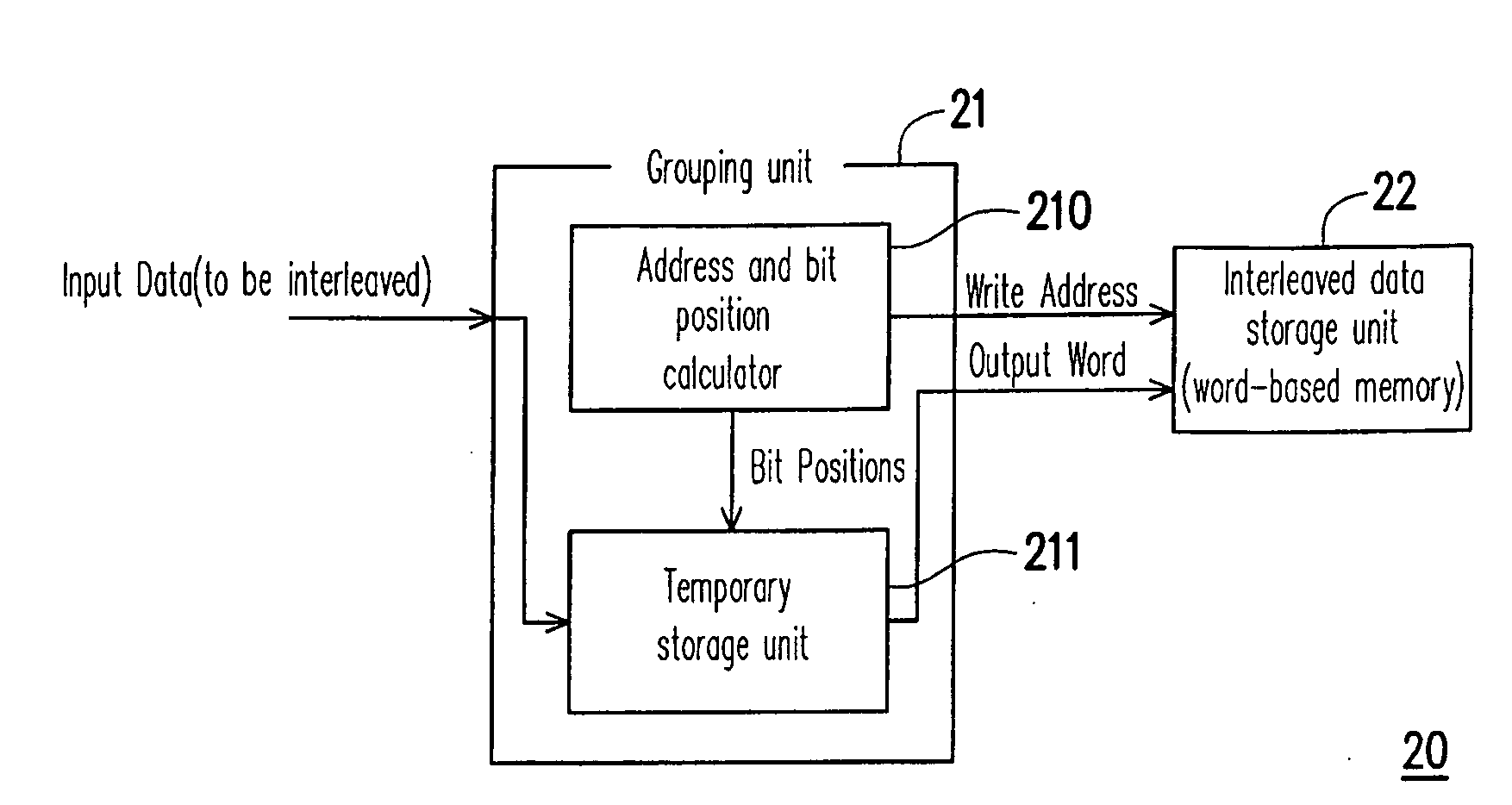
[0042]FIG. 2 is a basic block diagram showing one embodiment of the grouping bits interleaver 20. The grouping bits interleaver 20 comprises a grouping bits unit 21 and an interleaved data storage unit 22. The grouping bits unit 21 is coupled to the interleaved data storage unit 22. In this embodiment, the interleaved data storage unit 22 is a word-based memory. However it is not intended to limit the scope of the invention, and in some cases, the interleaved data storage unit 22 is a specified-data-format-based memory for fulfilling the requirement. For example, the data storage unit 22 may be a byte-based or double word-based memory array.
[0043]The grouping bits unit 21 is used to temporarily store ...
PUM
 Abstract
Description
Claims
Application Information