

Transfer Device and Image Forming Apparatus
- Summary
- Abstract
- Description
- Claims
- Application Information
AI Technical Summary
Benefits of technology
Problems solved by technology
Method used
Image

Examples
first embodiment
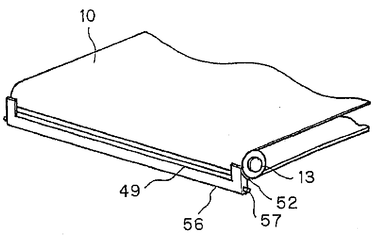
[0081]FIG. 12 shows the transfer belt sealing member 52 for preventing entanglement of the transfer belt sealing member 52 with the intermediate transfer belt 10.
[0082]In the first embodiment, the leading end surface 52a of the transfer belt sealing member 52 is a downwardly inclined surface from the upstream side toward the downstream side in the movement direction of the intermediate transfer belt 10. As a result, the transfer belt sealing member 52 is in contact with inclination relative to the thickness direction Y of the intermediate transfer belt 10 in the contact part between the transfer belt sealing member 52 and the end surface of the intermediate transfer belt 10. The leading end surface 52a of the transfer belt sealing member 52 and the end surface of the intermediate transfer belt 10 are in contact with inclination relative to the thickness direction Y of the intermediate transfer belt 10, and therefore, the frictional force between the transfer belt sealing member 52 a...
second embodiment
[0084]FIG. 13 shows the transfer belt sealing member 52 for preventing entanglement of the transfer belt sealing member 52 with the intermediate transfer belt 10.
[0085]In the second embodiment, the transfer belt sealing member 52 is formed in a plate-like shape. The flat part of the plate-like transfer belt sealing member 52 is brought into contact (surface contact) with the curved intermediate transfer belt 10 hung around the driven roller 13. As a result, the transfer belt sealing member contacts the end surface of the intermediate transfer belt diagonally relative to the thickness direction of the transfer belt, and the transfer belt sealing member is prevented from entangled with the intermediate transfer belt and damaged.
PUM
 Abstract
Description
Claims
Application Information