Control apparatus of vehicle drive apparatus
a technology of control apparatus and drive apparatus, which is applied in the direction of vehicle sub-unit features, road transportation, and gearing, etc., can solve the problems of energy loss due to energy conversion, inability to achieve control whereby, and inability to set the efficiency of motive power transmission to maximum efficiency, etc., to achieve the effect of improving drivability
- Summary
- Abstract
- Description
- Claims
- Application Information
AI Technical Summary
Benefits of technology
Problems solved by technology
Method used
Image
Examples
first embodiment
[0069]In the present embodiment, a case will be described in which the invention is applied as a vehicle drive apparatus mounted in a hybrid vehicle that is provided with two motor / generators, and is configured as an FF (front engine / front drive) vehicle.
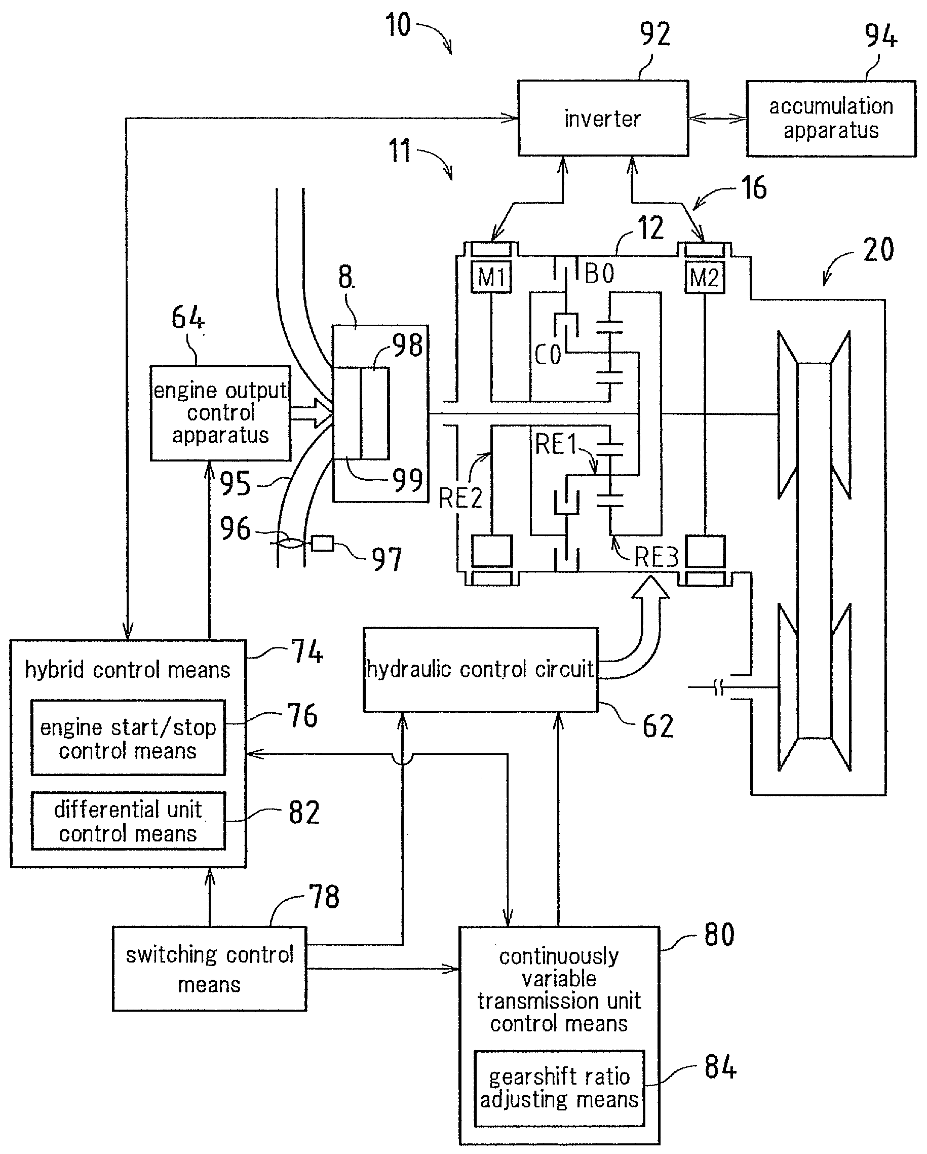
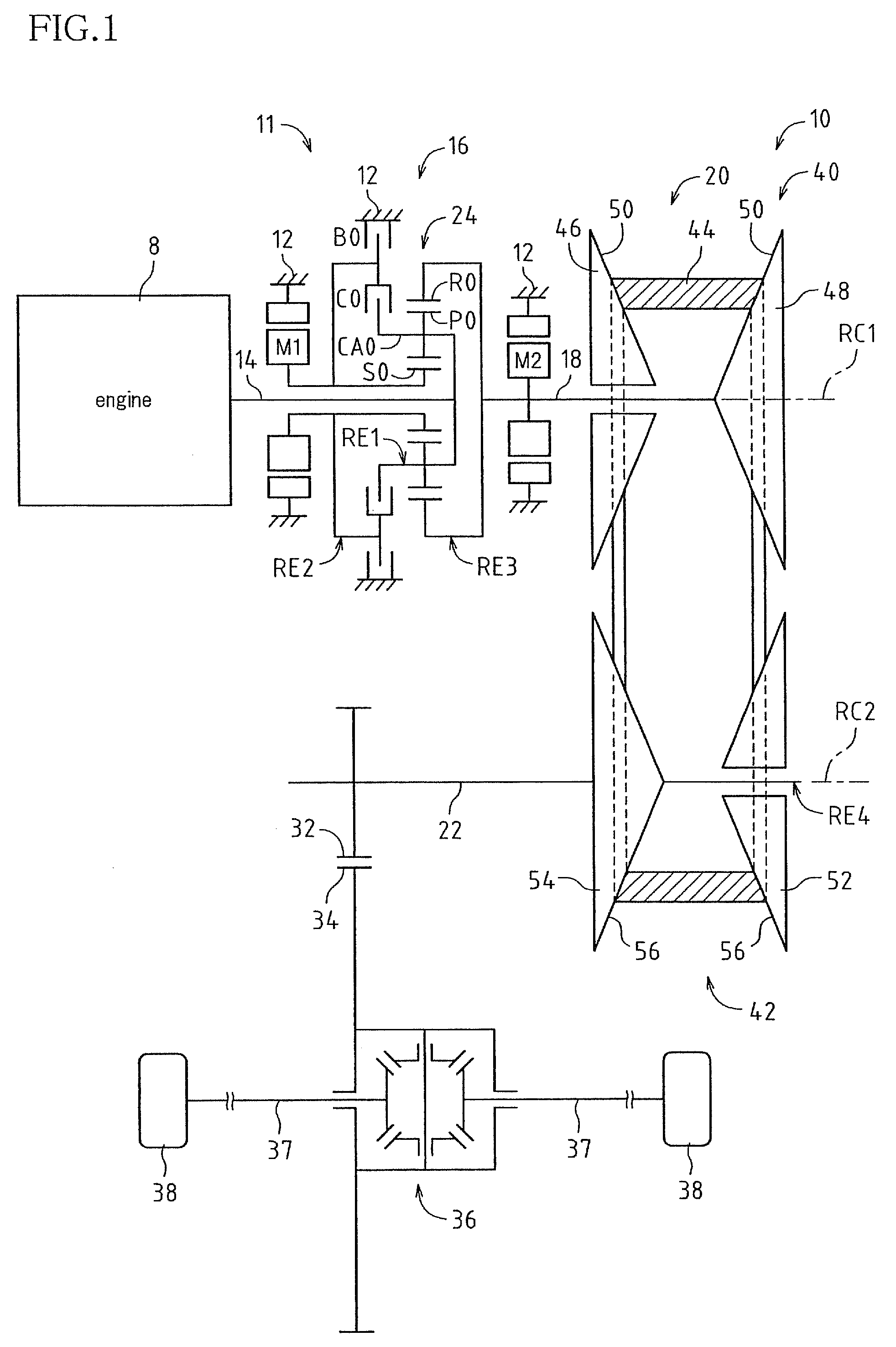
[0070]FIG. 1 is a skeleton view that shows a vehicle drive apparatus 10 (referred to below as simply a drive apparatus) that constitutes a hybrid system mounted in a hybrid vehicle according to the present embodiment.
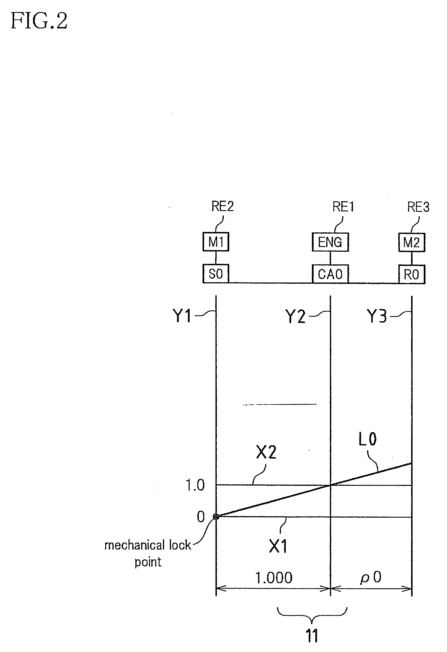
[0071]In FIG. 1, the drive apparatus 10 is provided with an input shaft 14 serving as an input rotation member, a differential unit 11 linked to the input shaft 14 directly or via an unshown pulse-absorbing damper (vibration damping apparatus), and a transmission member 18, which is an output rotation member of the differential unit 11, disposed in order on a first axis RC1 in a transmission case 12 (below, referred to as a ‘case 12’). Further, the drive apparatus 10 is provided with a mechanical continuously variable t...
second embodiment
[0171]Next is a description of a second embodiment. The present embodiment is characterized by the operation when engaging the switching clutch C0 and the switching brake B0 that are provided in the differential unit 11. Otherwise, the configuration of the drive apparatus 10 and the control operation are the same as in the above first embodiment, so here only the operation when engaging the switching clutch C0 and the switching brake B0 will be described.
[0172]In the present embodiment, the gear ratio adjusting means 82 changes the gear ratio of the continuously variable transmission unit 20 such that the total gear ratio γT is not changed when limiting the differential of the differential unit 11 (when engaging the switching clutch C0 or the switching brake B0). That is, prior to engaging the switching clutch C0 or the switching brake B0, the gear ratio of the continuously variable transmission unit 20 is changed, and thus, the revolution speed of the rotating elements (the differe...
third embodiment
[0196]FIG. 20 is a functional block diagram that illustrates relevant parts of control functions of the electronic control apparatus 60, in a third embodiment. In FIG. 20, a continuously variable transmission unit control means 116 is substituted for the continuously variable transmission unit control means 80 in FIG. 5, which is a functional block diagram of the first embodiment, and FIG. 20 differs from FIG. 5 in that an engine combustion system control means 112 and an engine combustion system determining means 114 are added. Below, mainly the differing points will be described.
[0197]The engine 8 of this embodiment is provided with a plurality of combustion systems having different specific fuel consumption properties, namely a stoichiometric combustion system that burns a mixture having a theoretical air-fuel ratio and a lean combustion system that burns a mixture in which fuel is diluted from the theoretical air-fuel ratio. In this engine 8, a combustion system appropriate to t...
PUM
 Abstract
Description
Claims
Application Information
 - R&D
- Intellectual Property
- Life Sciences
- Materials
- Tech Scout
- Unparalleled Data Quality
- Higher Quality Content
- 60% Fewer Hallucinations
Browse by: Latest US Patents, China's latest patents, Technical Efficacy Thesaurus, Application Domain, Technology Topic, Popular Technical Reports.
© 2025 PatSnap. All rights reserved.Legal|Privacy policy|Modern Slavery Act Transparency Statement|Sitemap|About US| Contact US: help@patsnap.com


