Maintenance scheduling system, maintenance scheduling method, and image forming apparatus

a maintenance scheduling and maintenance technology, applied in the direction of instruments, etc., can solve the problems of increasing the number of replacement work, increasing the cost of maintenance, and causing damage to users

Inactive Publication Date: 2009-08-20
KK TOSHIBA +1
View PDF5 Cites 20 Cited by
  • Summary
  • Abstract
  • Description
  • Claims
  • Application Information

AI Technical Summary

Problems solved by technology

Therefore, the risk of damages to a user caused by the unavailability of a product and the cost required for maintenance cannot be balanced.
If it is attempted to replace a component, which is highly likely to be broken, before the component reaches the end of durable life and reduce the risk of a product failure, replacement work has to be performed more than necessary and the cost of maintenance in

Method used


Image

  • Maintenance scheduling system, maintenance scheduling method, and image forming apparatus
  • Maintenance scheduling system, maintenance scheduling method, and image forming apparatus
  • Maintenance scheduling system, maintenance scheduling method, and image forming apparatus

Examples


second embodiment

[0122]A second embodiment of the present invention is explained below.

[0123]This embodiment is a modification of the first embodiment explained above and a basic system configuration of this embodiment is the same as that of the first embodiment. Components same as those already explained in the first embodiment are denoted by the same reference numerals and signs and explanation of the components is omitted.

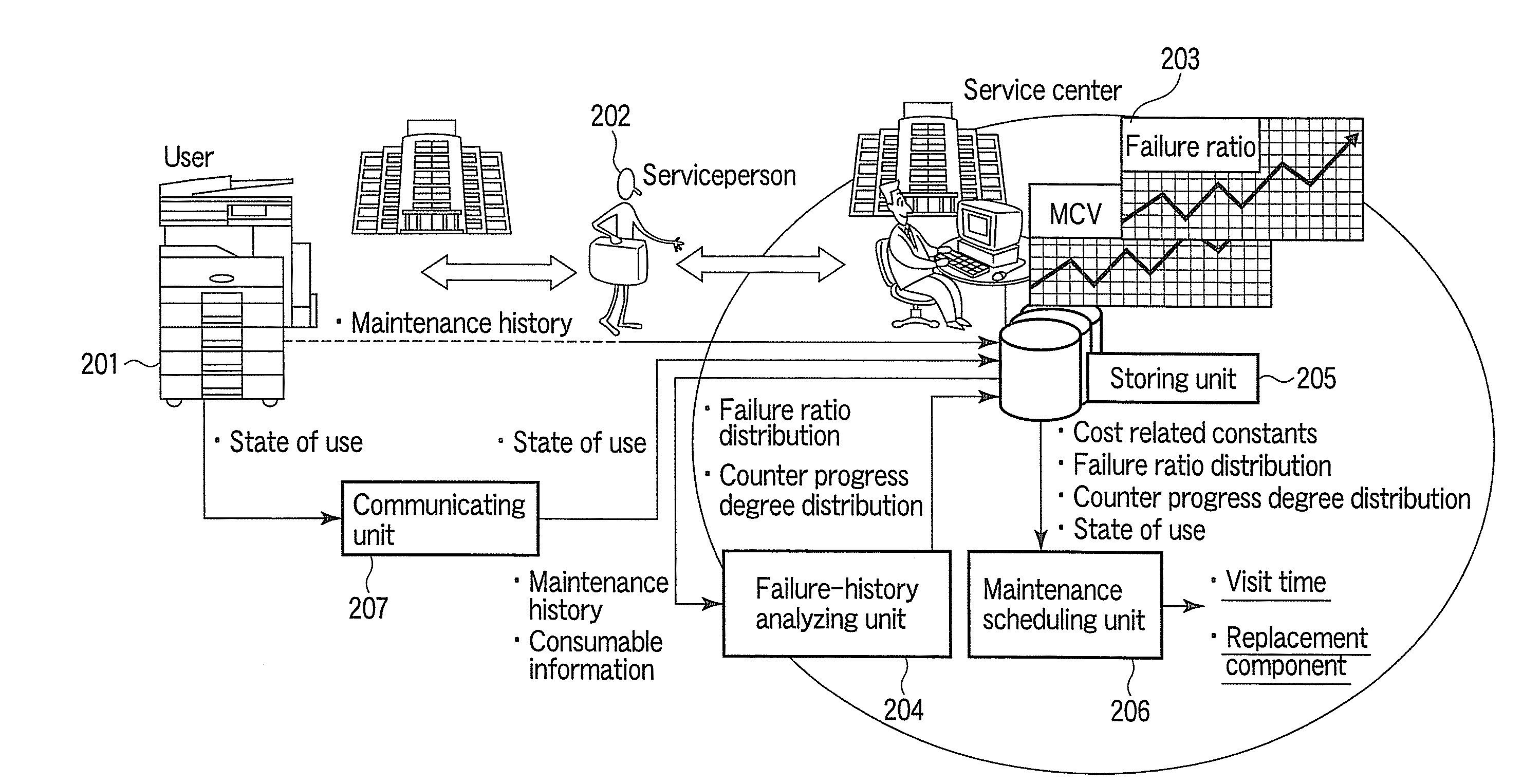
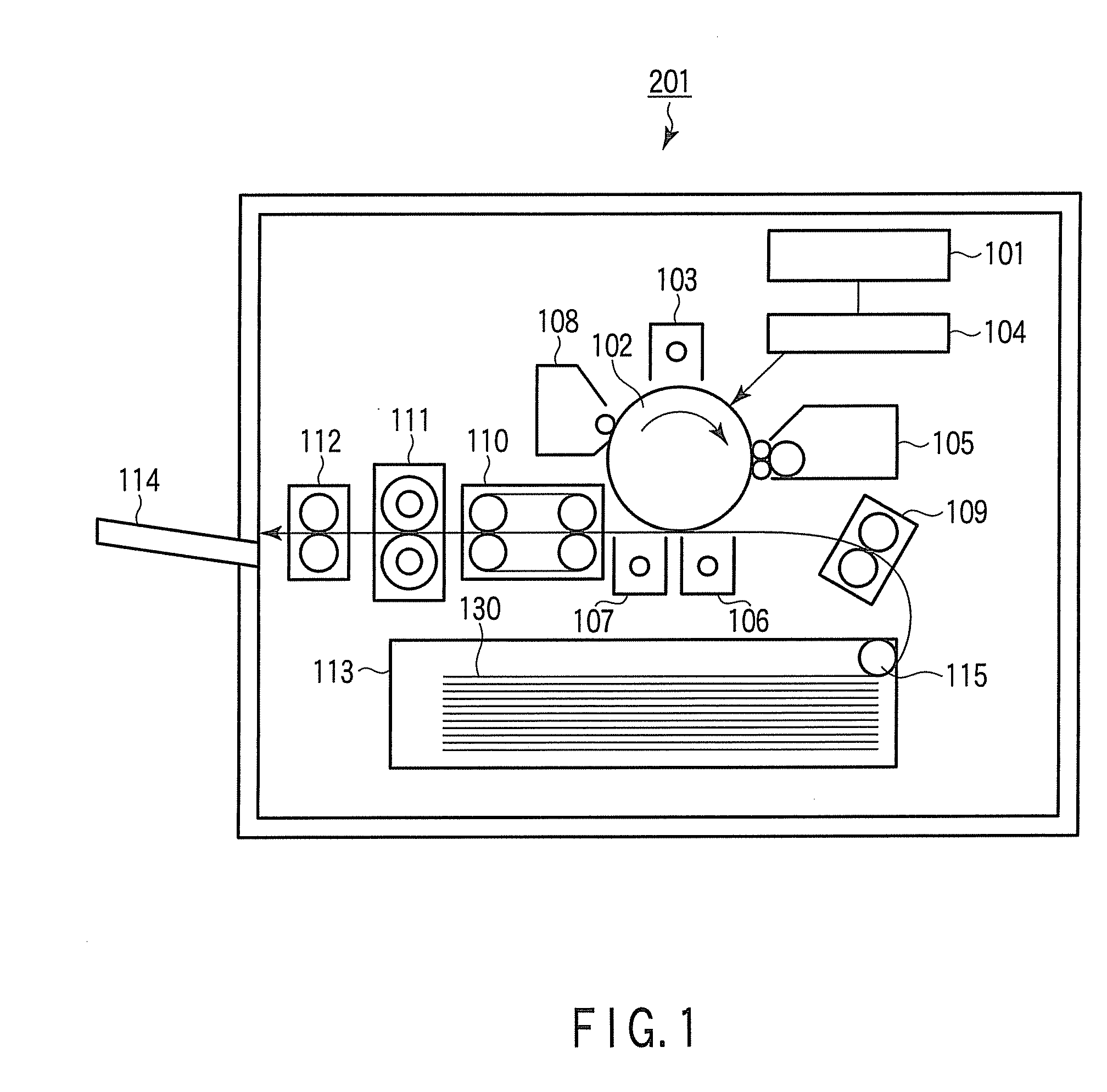
[0124]In this embodiment, the MFP 201 as a maintenance target apparatus includes a cartridge in which the photoconductive drum 102, the charger 103, the cleaner 108, the developing device 105, and the like are integrated as a unit. The cartridge is detachable from a main body of the MFP 201.

[0125]In the cartridge in which the various components are integrated, when one of the components of the cartridge is broken, it is necessary to replace the cartridge.

[0126]Therefore, in the “strategy deciding mode”, the “visit interval” and the “replacement interval” set in the “consumable s...

third embodiment

[0135]A third embodiment of the present invention is explained below.

[0136]This embodiment is a modification of the first embodiment explained above and a basic system configuration of this embodiment is the same as that of the first embodiment. Components same as those already explained in the first embodiment are denoted by the same reference numerals and signs and explanation of the components is omitted.

[0137]In this embodiment, in the “visit date presenting mode”, a calculation is periodically executed on all machines registered in advance.

[0138]The maintenance scheduling unit 206 has a schedule function periodically executed (e.g., at 6 o'clock everyday). The maintenance scheduling unit 206 executes the “visit date presenting mode” on all machines registered in the “machine” table 304 and updates the “visit schedule” table 311.

[0139]The serviceperson accesses the maintenance scheduling system 1 from the terminal 26 in the service center when a serviceperson comes to the office...

fourth embodiment

[0144]A fourth embodiment of the present invention is explained below.

[0145]This embodiment is a modification of the first embodiment explained above and a basic system configuration of this embodiment is the same as that of the first embodiment. Components same as those already explained in the first embodiment are denoted by the same reference numerals and signs and explanation of the components is omitted.

[0146]In this embodiment, in the “strategy deciding mode”, a “visit interval lower limit” and a “visit interval upper limit” are further calculated. The “strategy deciding mode” and the “visit date presenting mode” in this embodiment are explained below.

[0147]The maintenance scheduling unit 206 calculates and sets, for each of machines, a “visit interval”, a “visit interval lower limit”, a “visit interval upper limit”, and a “replacement interval” for each of consumables. The serviceperson 202 performs maintenance work on the basis of the “visit interval”, the “visit interval lo...


PUM


Abstract

A maintenance scheduling system that lays out a maintenance schedule for an image forming apparatus includes an actual-use-result acquiring unit that acquires actual use result information of consumables, a failure-probability-distribution estimating unit that estimates failure probability distributions of the consumables, a cost-related-constant acquiring unit that acquires cost related constants of the consumables, a first cost calculating unit that calculates, for each of plural visit interval values, cost per unit time required for the image forming apparatus, a visit-interval calculating unit that calculates the visit interval value giving minimum cost, a second cost calculating unit that calculates, for each of plural replacement interval values, cost per unit time required for the image forming apparatus, a replacement-interval calculating unit that calculates a calculated replacement interval value, and a maintenance-schedule presenting unit that presents the next visit time and at least one of the consumables to be replaced in the visit.

Description

CROSS-REFERENCE TO RELATED APPLICATIONS[0001]This application is based upon and claims the benefit of U.S. Provisional Applications No. 61 / 029,874, filed Feb. 19, 2008; No. 61 / 029,876, filed Feb. 19, 2008; and No. 61 / 036,581, filed Mar. 14, 2008.TECHNICAL FIELD[0002]The present invention relates to a technique for estimating failure time of a product including plural components and degrees of deterioration of the respective components and reflecting the failure time and the degrees of deterioration on a maintenance schedule.BACKGROUND[0003]In the related art, a maintenance schedule is laid out on the basis of the experience and the intuition of an individual serviceperson. Therefore, the risk of damages to a user caused by the unavailability of a product and the cost required for maintenance cannot be balanced.[0004]If it is attempted to replace a component, which is highly likely to be broken, before the component reaches the end of durable life and reduce the risk of a product fai...

Claims


Application Information

Patent Timeline
IPC IPC(8): G06Q10/00
CPCG06Q10/00G06Q10/06311G06Q10/0631
Inventor KAMISUWA, YOSHIKATSUNAKANE, RINTAROKATOU, HIROYO
Owner KK TOSHIBA
Why Eureka
Try Eureka