Ankle sprain reduction system

a technology of sprain reduction and ankle, applied in the field of ankle sprain reduction system, can solve the problems of ankle twisting, not providing the desired degree of reducing the occurrence and severity of ankle sprains

Inactive Publication Date: 2009-08-27
HARRIS NATHANIEL
View PDF34 Cites 25 Cited by
  • Summary
  • Abstract
  • Description
  • Claims
  • Application Information

AI Technical Summary

Benefits of technology

[0005]In accordance with this invention the ankle sprain reduction system includes brace having a base plate and medial and lateral support plates. The base plate is incorporated into and becomes part of the footwear or shoe by being located in the sole of the shoe and preferably in a recess in the sole. This creates a smooth sole surface. The base plate has medial and lateral sides extending upwardly from its lower base portion and extending below the respective malleolus terminating at the back of the shoe. The lateral and medial support plates are pivotally mounted to the lateral and medial side extensions of the base plate. The base plate is of a length to extend from about the heel to just proximal to the metatarsalphalangeal joints. In this manner, there is a maximum area of protection for the foot without interfering with toe movement.

Problems solved by technology

These types of sprains might result where, for example, the toes are bent too far causing hyperextension.
Other causes might result from stepping on an object which would cause a twisting of the ankle.
Such brace would be separate and distinct from the footwear and although it is intended to be customized for a particular wearer, it does not provide the desired degree of reducing the occurrence and severity of ankle sprains.

Method used


Image

  • Ankle sprain reduction system
  • Ankle sprain reduction system
  • Ankle sprain reduction system

Examples


Embodiment Construction

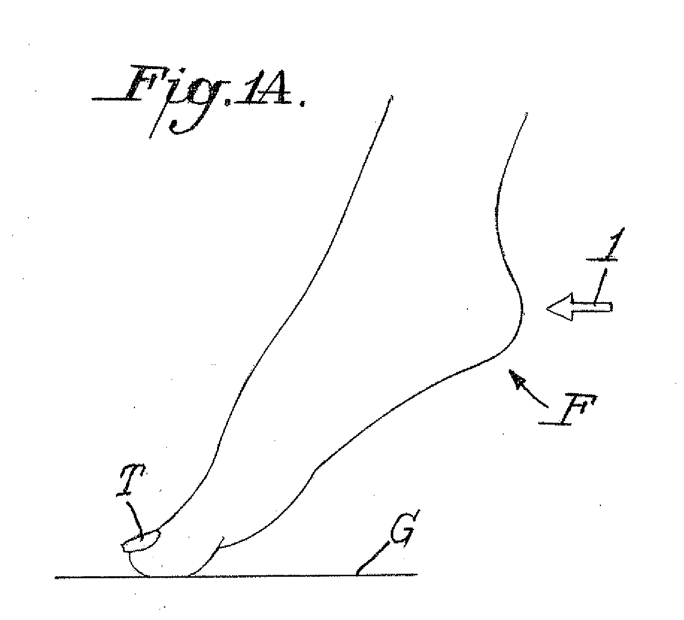
[0021]FIGS. 1 and 1A illustrate a human foot F which is in a condition that may be subject to hyperextension. If the toes T are pointed downwardly against the ground G, as particularly shown in FIG. 1A, the damaging forces (illustrated by the arrow 1) into the heel, strain the anterior ligaments, particularly in the area of the box B shown in FIG. 1. In order to avoid an ankle sprain resulting from hyperextension it would be desirable to provide some structure for preventing further backwards motion.

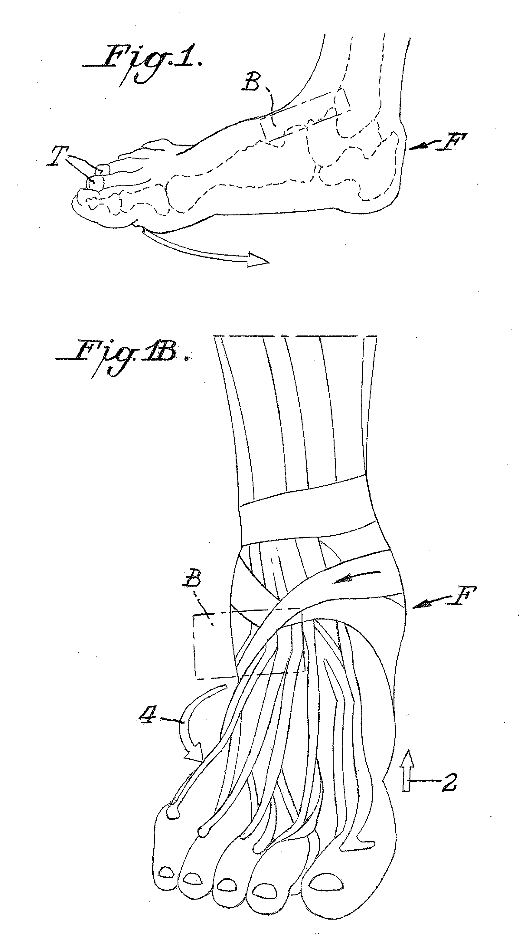
[0022]FIG. 1B shows the condition of a foot F which would be subject to inversion strains. Such inversion strains generally result from an upward force on the medial side of the foot from beneath as indicated by the arrow 2. This causes the foot to rotate as indicated by the arrow 4. Such rotation could result in ligament strain in the area indicated by the box B.

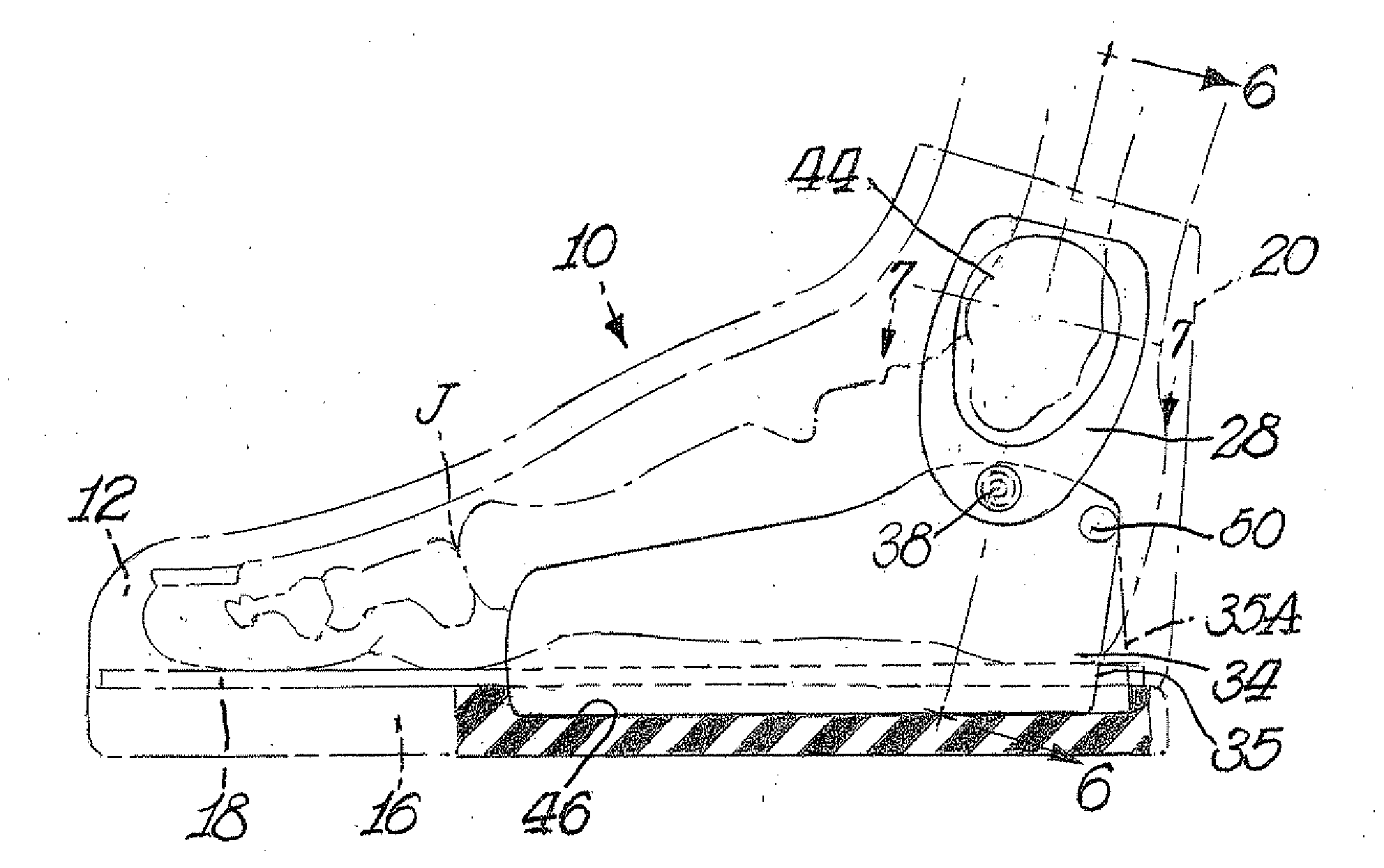
[0023]FIGS. 2-12 illustrate an ankle sprain reduction system 10 in accordance with this invention. System 10, in general, incl...


PUM


Abstract

An ankle sprain reduction system includes a shoe having a brace incorporated in the shoe. The brace has a base plate with medial and lateral sides extending upwardly from a lower base portion. Medial and lateral support plates are pivotally mounted to each of the sides at a location below the malleoli. The lower base portion is of a length that extends from the heel to just proximal to the metatarsalphalangeal joints of the foot.

Description

BACKGROUND OF INVENTION[0001]The present invention relates to reducing the severity of and preventing ankle sprain occurrences. Such ankle sprains are often encountered by individuals participating in athletics, although, such sprains can be encountered under other circumstances. Two types of sprains that occur are hyperextensions and inversion strains. These types of sprains might result where, for example, the toes are bent too far causing hyperextension. Other causes might result from stepping on an object which would cause a twisting of the ankle. It would be desirable if some form of brace or system could be provided to reduce the occurrence and severity of ankle sprains.[0002]Attempts have been made to address such ankle sprains in various manners. One general approach that has been used is to provide an ankle brace, such as one that might be customized for the particular wearer. Such brace would be separate and distinct from the footwear and although it is intended to be cust...

Claims


Application Information

Patent Timeline
Patent Type & Authority Applications(United States)
IPC IPC(8): A61F5/00
CPCA61F5/0127
Inventor HARRIS, NATHANIEL
Owner HARRIS NATHANIEL
Why Eureka
Try Eureka