
Dynamic device state representation in a user interface

a technology of user interface and device state, applied in the field of dynamic device state representation in the user interface, can solve the problems of cumbersome and inefficient installation of so many different device-specific drivers or utilities from different device providers on each host system, and achieve the effect of reducing the number of additional device provider supplied drivers and increasing the portability of devices

Inactive Publication Date: 2009-08-27
MICROSOFT TECH LICENSING LLC
View PDF54 Cites 72 Cited by
  • Summary
  • Abstract
  • Description
  • Claims
  • Application Information

AI Technical Summary

Benefits of technology

The patent describes a process for customizing the user experience of a device by providing custom device representations, such as icons or sounds, that are not included in standard device drivers or utilities. The process includes receiving information about the device's states and presenting a representation of the current state through a user interface. This allows device providers to customize the device's appearance and make it easier for different host systems to use. The process also allows users to update the device's state and receive notifications when new information is added. Overall, the patent provides a way for devices to have a unique user experience and improve compatibility with different host systems.

Problems solved by technology

The installation of so many different device-specific drivers or utilities from different device providers on each host system is cumbersome and inefficient.
Some device providers avoid the use of “standard” device drivers, such as those provided through an operating system, in part, because standard device drivers do not allow a vendor or manufacturer of the device to customize the user experience through custom icons associated with the device.

Method used


Image

  • Dynamic device state representation in a user interface
  • Dynamic device state representation in a user interface
  • Dynamic device state representation in a user interface

Examples


Embodiment Construction

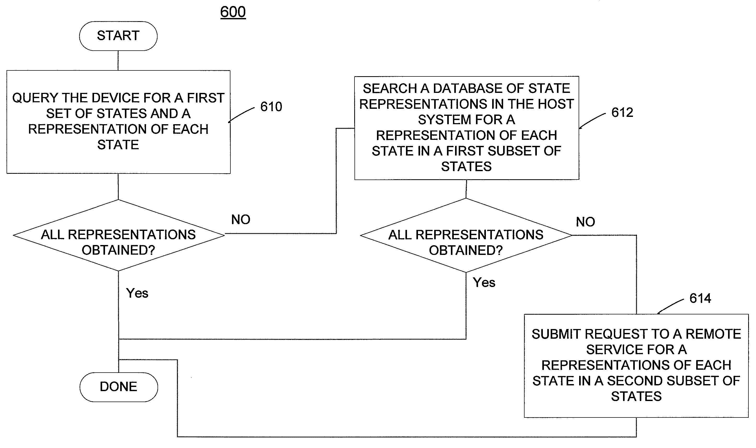
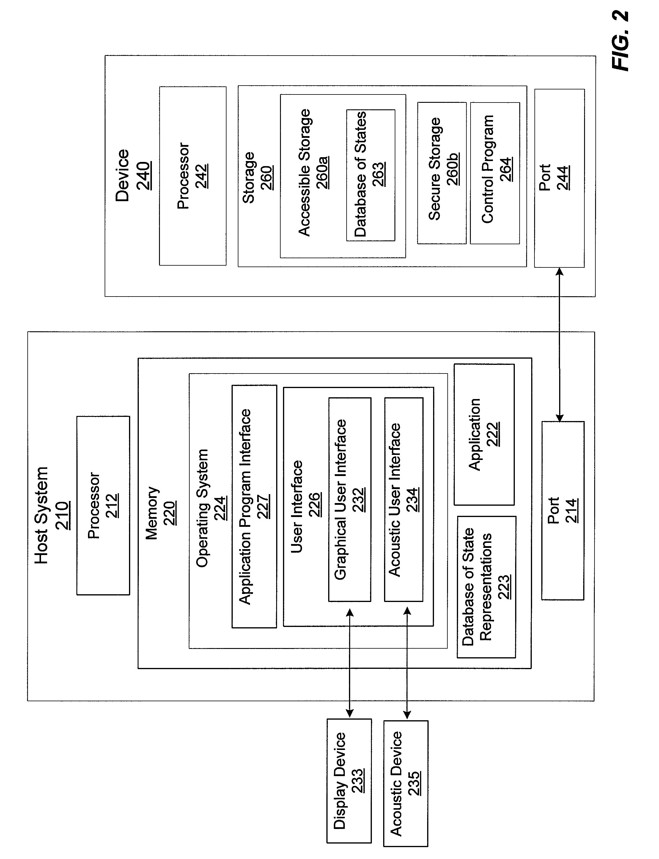
[0020]Embodiments of the invention provide a process for presenting a current state of a device having device storage connected with a host system. In embodiments of the invention, device manufacturers or vendors (referred to as “device providers” herein) may specify states of a device and one or more user interface (UI) elements (e.g. graphical elements, auditory elements, etc.) associated with each state through information stored on the device. A host system may dynamically present one or more interface elements associated with a current state of the device to a user without requiring that device-specific drivers or utilities from device providers be installed on the host system.

[0021]The one or more UI elements associated with a state of a device are elements of a representation of the state, also referred to as a state representation. A representation of the state includes the one or more UI elements associated with a state of a device, and may also include information regardin...


PUM


Abstract

Processes for presenting a current state of a device having device storage connected with a host system are provided. In some processes, device manufacturers or vendors define a set of operational states of a device and provide user interface (UI) elements of a custom representation of each state through information stored in the device storage. Initially, the set of states of the device and UI elements associated with each state are received from the device storage. Information regarding a current state is received from the device, and a representation of the current state, which includes the received UI elements, is presented on the host system. In other processes, UI elements of a representation of each state are obtained from a remote system using device identification information. In other processes, UI elements from the device, from the host system, and / or from a remote system are combined to form a state representation.

Description

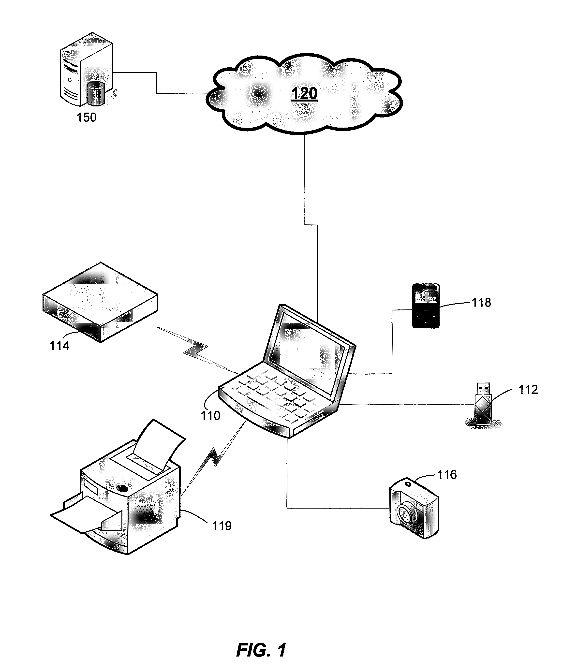
BACKGROUND[0001]Many different types of devices having storage, such as flash drives, digital cameras, digital media players, etc. communicate with a host system, such as a personal computer. A vendor or a manufacturer of such a device (referred to as a device provider herein) often provides a customized representation of the device for a user interface. A representation of the device for a user interface may be a graphical representation, a textual representation, a sound, etc. For example, a device provider may provide a custom icon, to be presented through the graphical user interface of the host system. A representation of the device, such as a custom icon, may change to indicate a change in a state of the device, or different representations may be used to indicate different states of the device. Frequently, one or more custom icons representing the device are included in a device-specific device driver, device-specific utility or other device-specific program supplied by the d...

Claims


Application Information

Patent Timeline
Patent Type & Authority Applications(United States)
IPC IPC(8): G06F3/048G06F7/10G06F17/30
CPCG06F3/04817
Inventor ALEXANDER, ROBINSADOVSKY, VLADIMIRRAMASUBRAMANIAN, NARASIMHAN
Owner MICROSOFT TECH LICENSING LLC
Learn More