Method of manufacturing panels having integrated heat pipes and/or inserts maintained by tongues

a technology of heat pipes and inserts, which is applied in the direction of indirect heat exchangers, laminated elements, lighting and heating apparatus, etc., can solve the problems of difficult extraction of pins from panels, large number of steps in the sequence, and quick limitation, so as to preserve the accuracy of positioning of heat pipes. , the effect of improving the situation

Inactive Publication Date: 2009-09-03
THALES SA
View PDF8 Cites 6 Cited by
  • Summary
  • Abstract
  • Description
  • Claims
  • Application Information

AI Technical Summary

Benefits of technology

[0010]Since no known method provides full satisfaction, it is the object of the invention to improve the situation by proposing a fabrication method that does not require the use of pins, by preserving the accuracy of positioning of the heat pipes and / or inserts (or even improving it so that it becomes lower than or equal to 1 mm), and by offering the possibility of incorporating a large quantity of heat pipes and / or inserts, typically between 30 and 40, or even more.

Problems solved by technology

However, it is quickly limited in the case of a large number of heat pipes and / or inserts and a large panel.
Regardless of the method used, the number of steps in the sequence is too large and the extraction of the pins from the panel proves to be difficult, and even sometimes virtually impossible due to the action of the adhesive on the parts of the pins or housings thereof where the protection may be damaged during handling and / or which are poorly protected.
It is certainly possible to improve the situation, for example by using taper pins and / or holes comprising a flat, but this increases the cost without necessarily reducing the number of steps in the sequence.

Method used


Image

  • Method of manufacturing panels having integrated heat pipes and/or inserts maintained by tongues
  • Method of manufacturing panels having integrated heat pipes and/or inserts maintained by tongues
  • Method of manufacturing panels having integrated heat pipes and/or inserts maintained by tongues

Examples


Embodiment Construction

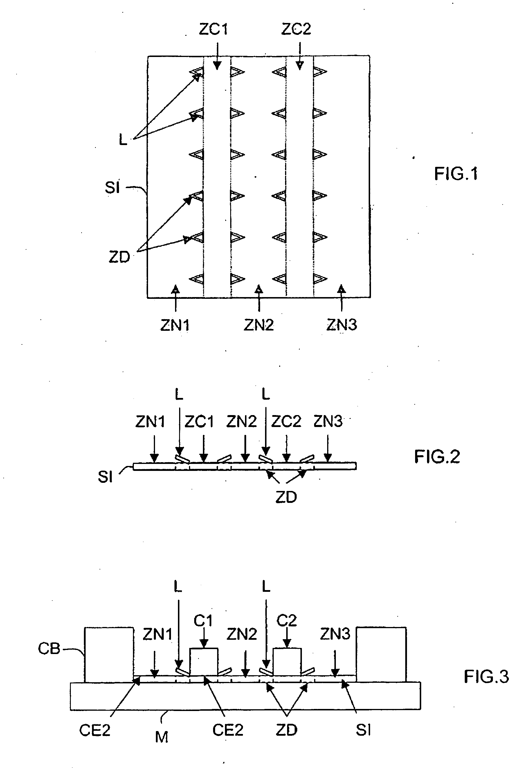
[0042]The appended drawings may not only serve to complete the invention, but also contribute to its definition, if necessary. It is important to note that in FIGS. 1 to 7, the respective dimensions of the various elements are not representative of their actual and relative dimensions.

[0043]It is the object of the invention to allow the simplified fabrication of panels having built-in heat pipe(s) and / or insert(s), through the non-use of immobilization pins.

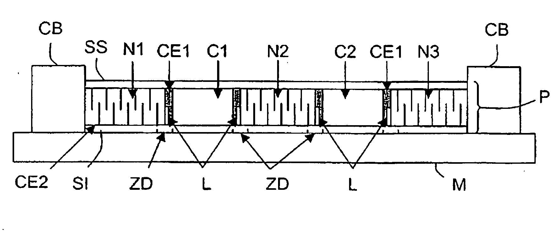
[0044]In the following discussion, it is considered as a nonlimiting example that the panels have built-in heat pipes and are intended to be installed on spacecraft, such as satellites for example. However, such panels may comprise only inserts (instead of heat pipes) or a mixture of heat pipe(s) and insert(s). Moreover, these panels may be installed on other equipment or systems, particularly in the aeronautic and automotive fields, insofar as a heat pipe or an insert must be integrated in a panel. Such panels may have any size,...


PUM

PropertyMeasurementUnit
angleaaaaaaaaaa
angleaaaaaaaaaa
angleaaaaaaaaaa

Abstract

A method, dedicated to the fabrication of the panels having built-in heat pipe(s) and/or insert(s) (P), consists in a) providing a bottom plate (SI) comprising, in selected places on either side of the heat pipe or insert accommodation zones, tabs (L) which are substantially flat and suitable for being straightened above its upper face, b) partially straightening the tabs (L) toward the accommodation zones, c) positioning the heat pipes and/or the inserts (C1, C2) in each accommodation zone between the tabs (L) and in contact with the upper face of the bottom plate (SI), d) terminating the straightening of the tabs (L) so that they are pressed against the side faces of the heat pipes and/or inserts (Ci), e) depositing a selected thickness of a first adhesive against the side faces of the heat pipes and/or the inserts (Ci), f) positioning separating structures (N1-N3), substantially having the same height as that of the heat pipes and/or the inserts (C1, C2) on either side of the side faces of each heat pipe and/or insert and in contact with the upper face of the bottom plate (SI), and g) placing an upper plate (SS) above the heat pipes and/or inserts (C1, C2) and the separating structures (N1-N3) and in contact therewith.

Description

CROSS-REFERENCE TO RELATED APPLICATIONS[0001]The present Application is based on International Application No. PCT / FR2007 / 050691, filed on Jan. 25, 2007, which in turn corresponds to French Application No. 0650255 filed on Jan. 25, 2006, Each of these applications are hereby incorporated by reference in their entirety into the present application.FIELD OF THE INVENTION[0002]The invention relates to panels having built-in heat pipe(s) and / or insert(s), and more precisely the methods for fabricating such panels.BACKGROUND OF THE INVENTION[0003]In the context of the present invention, “panel having built-in heat pipe(s) and / or insert(s) means a panel comprising plates called bottom and upper plates, between which heat pipes and / or inserts are immobilized (for example two or three, or even thirty or forty), separated from one another by separating structures, generally of the honeycomb type. Furthermore, in the context of the present invention, “insert” means a block, for example of alu...

Claims


Application Information

Patent Timeline
Patent Type & Authority Applications(United States)
IPC IPC(8): F28D15/02B23P15/26
CPCB23P15/26B23P2700/09F28D15/02Y10T29/49353F28D15/0275F28F2275/025F28F2275/12F28D15/0233
Inventor MAUDUIT, DANIEL
Owner THALES SA
Why Eureka
Try Eureka