
Laser cutting machine with focusing laser head

A technology of laser cutting machine and laser cutting head, which is applied in the direction of laser welding equipment, manufacturing tools, welding equipment, etc., can solve the problem that optical fibers cannot cut thick plates, and achieve the effects of avoiding adverse effects, ensuring accuracy, and prolonging service life

Inactive Publication Date: 2018-10-16
沧州领创激光科技有限公司
View PDF0 Cites 5 Cited by
  • Summary
  • Abstract
  • Description
  • Claims
  • Application Information

AI Technical Summary

Problems solved by technology

[0003] The purpose of the present invention is to provide a laser cutting machine with an adjustable focus laser head. The laser cutting head of the laser cutting machine can set the focus size, and set different focus diameters according to different materials and plate thicknesses, which solves the problem that optical fibers cannot cut thick Board problem; with focus function, when cutting workpieces with different material thicknesses, the focus position can be adjusted only by parameter setting, without manual adjustment

Method used


Image

  • Laser cutting machine with focusing laser head
  • Laser cutting machine with focusing laser head
  • Laser cutting machine with focusing laser head

Examples


Embodiment 1

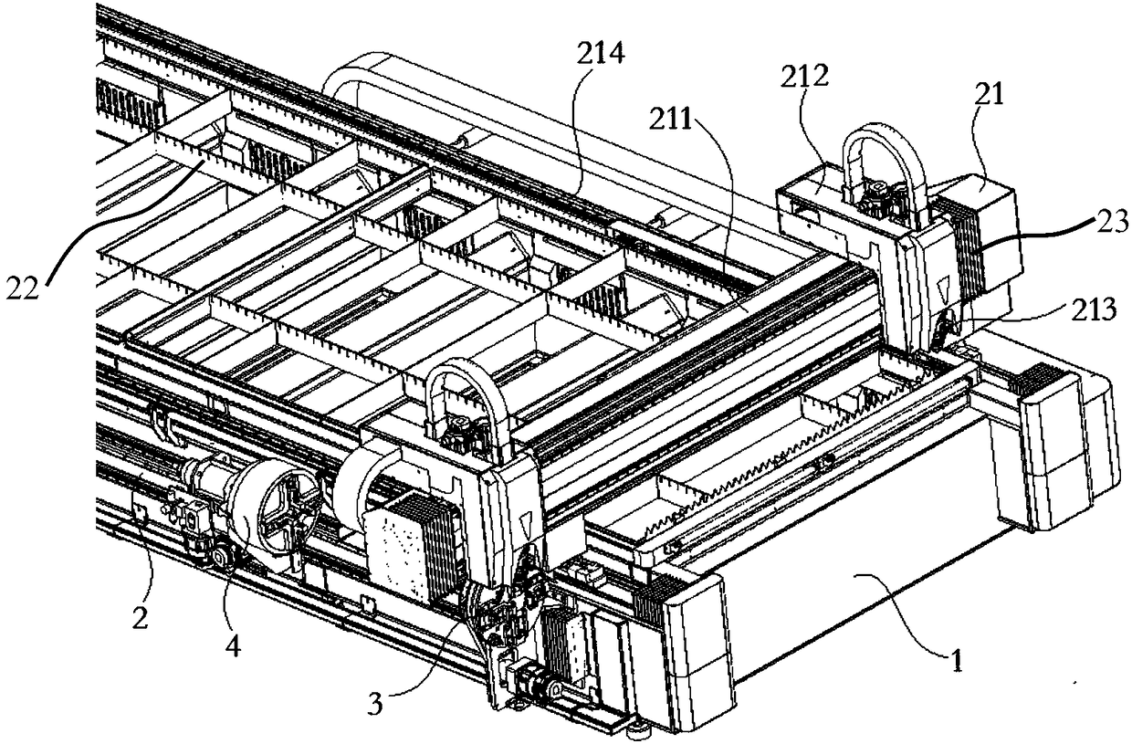
[0034] Embodiment 1: A laser cutting machine with an adjustable focus laser head, including a base 1, side guide rails 2 relatively arranged on both sides of the base 1, a front support mechanism 3, a rear rotation mechanism 4 and a cutting mechanism 21, the The cutting mechanism 21 is movably installed on the upper surface of the base 1, the rear rotating mechanism 4 is mounted on one side surface of the base 1 through the guide rail 2 and can move forward and backward along the guide rail, and the front supporting mechanism 3 is parallel to the rear rotating mechanism 4 set, installed at one end of the base 1;

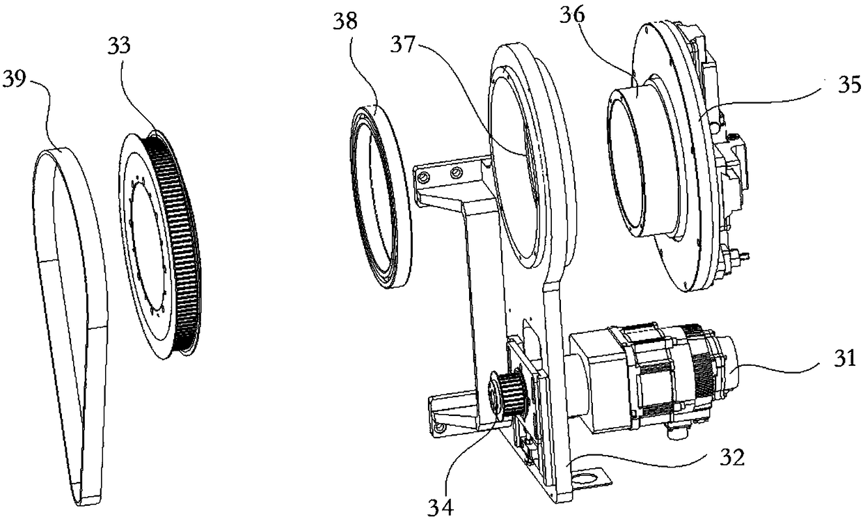
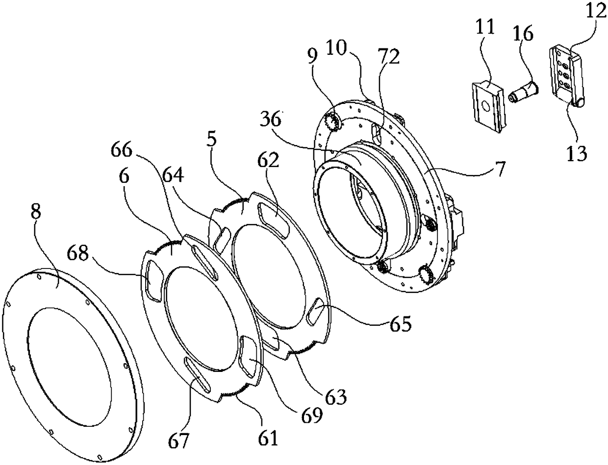
[0035] The front end support mechanism 3 further includes a motor 31, a support base 32, a large synchronous pulley 33, a small synchronous pulley 34 and a rotating disk 35, and the motor 31 and the small synchronous pulley 34 are respectively installed on both sides below the support base 32, The output shaft of this motor 31 passes through the support base 32 and i...

Embodiment 2

[0049] Embodiment 2: A laser cutting machine with an adjustable focus laser head, including a base 1, side guide rails 2 relatively arranged on both sides of the base 1, a front support mechanism 3, a rear rotation mechanism 4 and a cutting mechanism 21, the The cutting mechanism 21 is movably installed on the upper surface of the base 1, the rear rotating mechanism 4 is mounted on one side surface of the base 1 through the guide rail 2 and can move forward and backward along the guide rail, and the front supporting mechanism 3 is parallel to the rear rotating mechanism 4 set, installed at one end of the base 1;

[0050] The front end support mechanism 3 further includes a motor 31, a support base 32, a large synchronous pulley 33, a small synchronous pulley 34 and a rotating disk 35, and the motor 31 and the small synchronous pulley 34 are respectively installed on both sides below the support base 32, The output shaft of this motor 31 passes through the support base 32 and i...


PUM


Abstract

The invention discloses a laser cutting machine with a focusing laser head. The laser cutting machine with the focusing laser head comprises a base, side guide rails, a front end supporting mechanism,a rear end rotating mechanism and a cutting mechanism, wherein the side guide rails are oppositely arranged on the surfaces of the two sides of the base; the cutting mechanism is movably installed onthe upper surface of the base, and the rear end rotating mechanism is installed on the surface of one side of the base through a guide rail and can move back and forth along the guide rail; the frontend supporting mechanism and the rear end rotating mechanism are arranged in parallel and are arranged at one end of the base, a main shaft is arranged on the rear end surface of the large disc, anda small gear shaft is connected to the inner wall of a through hole of a bearing seat through a bearing; and an outer locking nut is tightly connected to four clamping pieces of a locking bearing gland through threads, so that small gear shafts are clamped and positioned. According to the laser cutting machine with the focusing laser head, the laser cutting head of the laser cutting machine can set the focal point size, different focal point diameters are set according to different materials and plate thicknesses, and the problem that the thick plates cannot be cut by the optical fibers is solved; and the machine has the focusing function and can be used for cutting a workpiece with different material thicknesses, the position of the focal point can be adjusted only by parameter setting, and manual adjustment is not needed.

Description

technical field [0001] The invention relates to a laser cutting machine with an adjustable focus laser head, belonging to the technical field of laser cutting. Background technique [0002] As a fast and efficient processing method, laser cutting has been widely used in various industrial fields. Laser cutting machine is a kind of equipment for cutting and processing with laser beam, mainly including laser generator, beam expander, focusing mirror, worktable, plane fixture or rotating fixture and other related control units, in which the rotating fixture is used for clamping When cutting the pipe, the rotation of the fixture drives the pipe to rotate, and the laser cutting machine cuts the pipe. Due to the high-precision characteristics of laser cutting, how to make the rotating fixture run smoothly and achieve precise cutting of the pipe has become the focus of discussion among engineers. Contents of the invention [0003] The purpose of the present invention is to provi...

Claims


Application Information

Patent Timeline
Patent Type & Authority Applications(China)
IPC IPC(8): B23K26/046B23K26/073B23K26/38B23K26/70
CPCB23K26/046B23K26/073B23K26/38B23K26/702
Inventor 李超文国民白素涛严巍
Owner 沧州领创激光科技有限公司
Learn More