Automated precision small object counting and dispensing system and method

a technology of automatic counting and small objects, applied in the field of prescription filling systems, can solve the problems of handicapped accuracy of optical sensors in several ways, and achieve the effect of preventing overfilling

Active Publication Date: 2009-09-03
TENSION INT
View PDF22 Cites 65 Cited by
  • Summary
  • Abstract
  • Description
  • Claims
  • Application Information

AI Technical Summary

Benefits of technology

[0012]The foregoing and other objects of this invention are achieved by providing a small object dispenser adapted to receive a canister of objects such as pills, the canister being coupled atop it through a secure, bar-code matched gate operated by a central controller. A hopper below the gate directs smaller quantities of objects into a charge block adapted to measure out a select number of objects into an angularly disposed, circular counter where they accumulate atop a movable plate forming the bottom of the counter. The plate bears slots around its perimeter adjacent the cylindrical walls of the counter. As the central controller operates a servo motor to rotate the plate in measured increments, it urges a precise count of objects from the bottom of the counter to a port through which they fall one at a time into a receptacle such as a prescription bottle. Orientation means on the interior of the walls orient objects so that only a single object may fall into each slot, thereby preventing overfilling. A separate sensor counts the objects as they fall to verify quantity and guard against underfilling due to empty slots.

Problems solved by technology

Accuracy of optical sensors, however, may be handicapped in several ways.
First, pills falling through the space where the sensor is focused may stick together or otherwise group to mislead the sensor into thinking only a single pill fell when in fact more than one did.

Method used


Image

  • Automated precision small object counting and dispensing system and method
  • Automated precision small object counting and dispensing system and method
  • Automated precision small object counting and dispensing system and method

Examples


Embodiment Construction

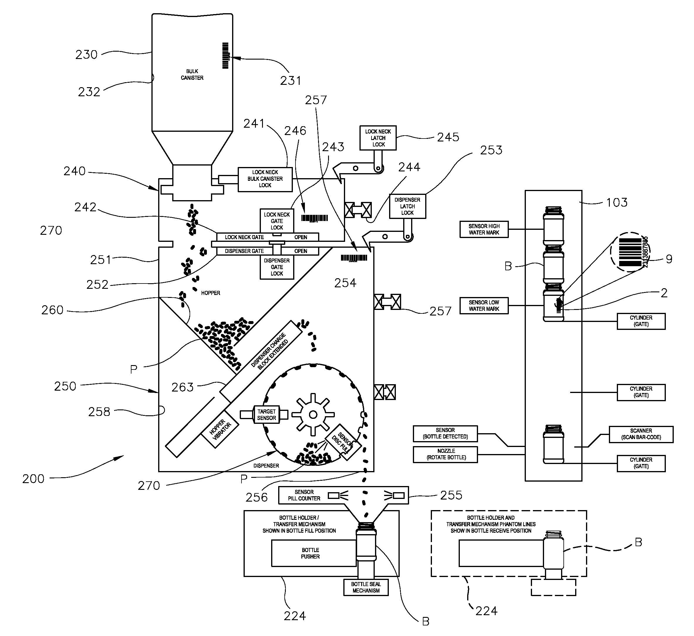
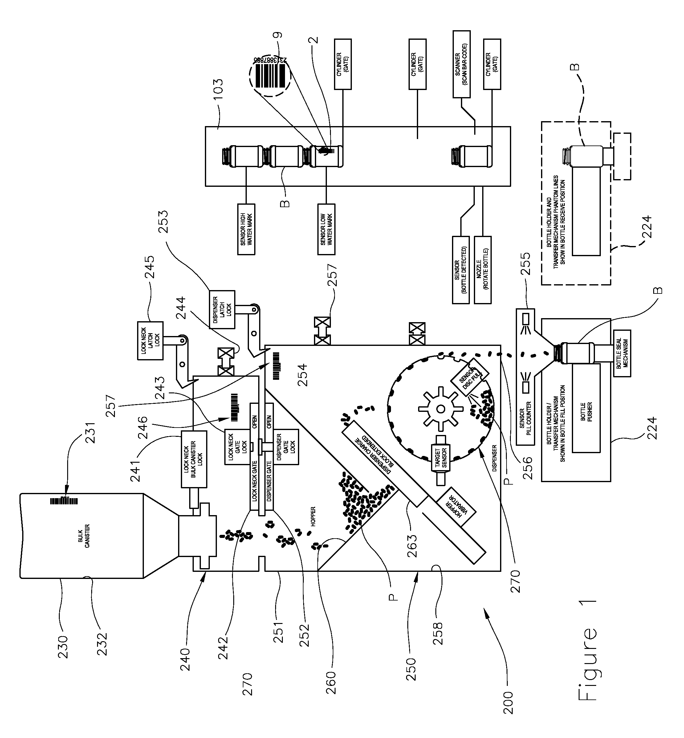
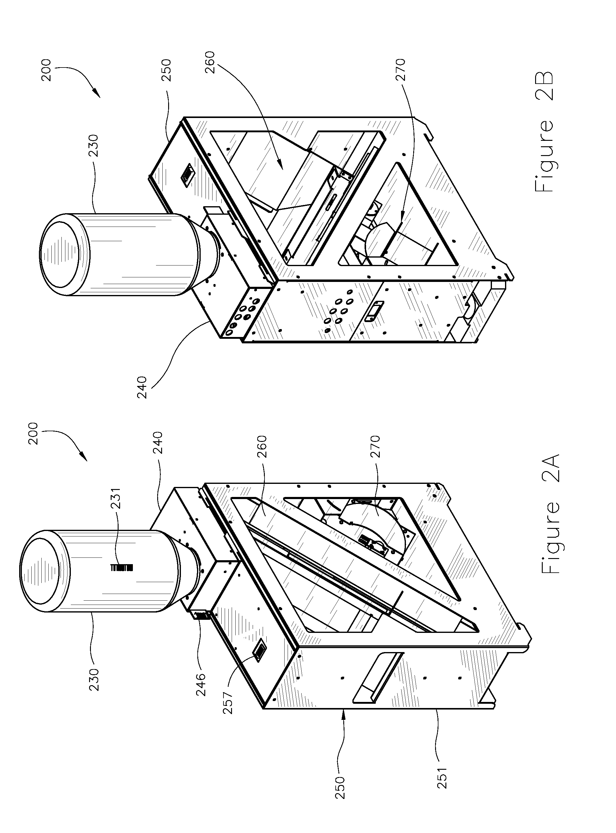
[0029]With reference now to the figures, and in particular to FIGS. 1-4, a single dispenser unit 200 integrates with bottle train BT to dispense objects, namely pills P, into bottles B in measured quantities according to a predetermined requirements (individual prescriptions). NOTE: as mentioned above, the present invention, though adaptable for the counting and dispensing of myriad small objects, will be discussed hereinafter in this disclosure primarily in the context of pharmaceuticals and prescription filling, except where special notice is needed for other objects. One having ordinary skill in the art will recognize that the counting and dispensing of any such small objects is considered to be within the spirit and scope of the present invention.

[0030]Dispenser unit 200 comprises chassis 250 coupled to bulk canister 230 through lock neck 240 and containing within its interior 258 hopper system 260 and counter 270 adapted to accumulate pills P from bulk canister 230 for counting...


PUM


Abstract

A small object dispenser adapted to receive a canister of objects such as pills, the canister being coupled atop it through a secure, bar-code matched gate operated by a central controller. A hopper below the gate directs smaller quantities of objects into a charge block adapted to measure out a select number of objects into an angularly disposed, circular counter where they accumulate atop a movable plate forming the bottom of the counter. The plate bears slots around its perimeter adjacent the cylindrical walls of the counter. As the central controller operates a servo motor to rotate the plate in measured increments, it urges a precise count of objects from the bottom of the counter to a port through which they fall one at a time into a receptacle such as a prescription bottle. Orientation means on the interior of the walls orient objects so that only a single object may fall into each slot, thereby preventing overfilling. A separate sensor counts the objects as they fall to verify quantity and guard against underfilling due to empty slots.

Description

BACKGROUND OF THE INVENTION[0001]1. Field of the Invention[0002]This invention relates generally to automated small object counting and dispensing systems and particularly to prescription filling systems. More particularly, this invention relates to such a system having automated pill and capsule counting apparatus and a bulk pill and capsule security, matching and verification system.[0003]2. Description of Related Art[0004]With increasing demand for orally administered medicine in recent years, automated prescription filling systems have come into their own worldwide. Such systems draw from bulk canisters of pills to count out exact quantities for smaller containers individualized to particular patients. Aside from the need to track through such systems the particular bottle to be associated with said patient, accurate counting systems are required to assure that neither too many nor too few pills are dispensed into the bottle.[0005]Many systems rely upon optical sensors to count ...

Claims


Application Information

Patent Timeline
Patent Type & Authority Applications(United States)
IPC IPC(8): B65D83/04
CPCA61J7/02B65B5/103B65B57/20B65B35/08
Inventor TERZINI, ROBERT
Owner TENSION INT
Why Eureka
Try Eureka